- Building a 3D Digital Clock with ArduinoPosted 4 months ago
- Creating a controller for Minecraft with realistic body movements using ArduinoPosted 5 months ago
- Snowflake with ArduinoPosted 5 months ago
- Holographic Christmas TreePosted 5 months ago
- Segstick: Build Your Own Self-Balancing Vehicle in Just 2 Days with ArduinoPosted 6 months ago
- ZSWatch: An Open-Source Smartwatch Project Based on the Zephyr Operating SystemPosted 7 months ago
- What is IoT and which devices to usePosted 7 months ago
- Maker Faire Rome Unveils Thrilling “Padel Smash Future” Pavilion for Sports EnthusiastsPosted 7 months ago
- Make your curtains smartPosted 8 months ago
- Configuring an ESP8266 for Battery PowerPosted 8 months ago
How to build your tech Laser Harp (step by step)

We rebuild the ancient musical instrument in an ultra-technological version, where instead of the strings we put laser beams, interrupting them with the passage of the fingers the notes are produced.
The harp is a string instrument with a soft, harmonious and relaxing sound, which has its roots in the most remote history dating back to the civilizations of the Greeks and the Latins and perhaps even earlier; we find it again today in symphony orchestras and also in chamber music concerts. Like all stringed instruments, it produces the sound by pinching or stretching and releasing a certain number of strings with the fingers, kept in tension by the frame in which they are mounted: a frame normally made of wood, with an almost triangular characteristic shape.
Without objecting to the classical instrument, we decided to revisit the structure by replacing the strings with something futuristic, because we are talking about laser beams; this is how our Harp Laser was born, which is an electronic and highly technological musical instrument, in whose design we have, so to speak, “pulled in” the inevitable Arduino and its accompanying hardware, as well as a bit of imagination to put together the frame, obtained from a set of appropriately assembled plexiglass details.
To give a scenographic touch we have also foreseen the possibility of piloting, when the harp is in operation, a smoke machine that brings out the red laser beams, giving body and texture to the strings and making them look as solid as those of the traditional harp.
THE PROJECT
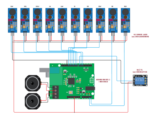
Let’s immediately see how our techno-instrument is composed, starting with electronics; the latter is composed of an Arduino UNO rev.3 board that interfaces with a group of laser sensors used to understand when we interrupt the beam.
We will explain shortly how the system works and why a laser can turn into a virtual string of an electronic harp.
In addition to Arduino and laser strings, we have a MIDI shield, which is the actual sound generator; eh, as such, because the harp must make sound and therefore must be able to generate sounds, so it is in our project:
- the laser sensors constitute the input devices, to equip the functioning of the sensor with respect to the disturbances and the light in the environment: in fact if the laser were switched on constantly, DOUT would present (in case of light arriving on the phototransistor after being reflected) a voltage influenced by ambient light, since the phototransistor could be constantly conducting if it was sufficiently illuminated or struck by other light radiations included in its sensitivity spectrum. Instead, by emitting light pulses at a certain frequency, we can, using a filter-equipped receiver module, ensure that it only detects them, discarding continuous light components.
The laser sensor circuit is supplied with a voltage that can be between 2.5 and 12 Vdc, thanks to the presence of an integrated switching regulator based on the integrated PT1301.

Let us now turn to the heart of the musical instrument, which is a shield based on the integrated VS1053B from VLSI, already used in other projects in the past and capable of generating a certain number of musical notes synthesizing the sounds of a large number of musical instruments and melodic ( including the harp and the organ) and percussion, behind commands given by a data channel; accepted commands can be of various formats, including the popular MIDI, which has been the standard used for decades to interface music synthesizers and electronic keyboards to the PC.
Let’s start by analyzing the circuit diagram of the circuit, found in these pages.
Everything revolves around the integrated U1, which is our VS1053B; the latter is together a CODEC / multistandard decoder (it contains codes and data memory for the Ogg Vorbis, MP3, AAC, WMA and WAV PCM + ADPCM audio decoding codecs) and a complete standard MIDI synthesizer. Thanks to software plug-ins, the chip can also implement FLAC lossless decoding as well as that of a high-quality recording in Ogg Vorbis format.
All this uses a serial interface for communication with the host device (the microcontroller that governs the synthesizer), which can also be configured in SPI-bus mode. In reality the VS1053B integrates a complex of serial interface that counts two interfaces: one of control (SCI = Serial Command Interface) that serves to command the functioning of the chip and that in our case is the one through which Arduino (but any microcontroller could do it) …) gives its own commands and a data transfer (SDI = Serial Data Interface) thanks to which the VS1053B can transfer or acquire streaming data to another external device or from it. Of the two, the one that can be configured to work in TTL or SPI serial mode is the SCI, that is the control interface.
The integrated sound synthesizer is based on a VLSI proprietary DSP (Digital Signal Processor), called the VS_DSP. The synthesized sounds are converted by a multi-rate stereo DAC, to whose output there are an audio preamplifier stage and a stereo output filter.
The integration also supports the PCM / ADPCM audio encoding, using as an input stage amplified the microphone amplifier (for those who want to use a microphone) or by picking up the signal from a line input and sending it to an A / D converter stereo. In the diagram we see that Arduino manages the VS1053B through the serial port used as UART, which in U1 refers to pins 26 (RX) and 27 (TX) connected respectively to Arduino’s digital pins D3 and D2; the latter also manages the U1 reset, via D4, so as to prepare it for receiving commands.
The three lines in question are equipped with pull-up on the side of the VS1053 and are controlled by the Arduino pins via series resistors; three jumpers (JRX, JTX and JRST) on the shield circuit board allow disconnecting them if necessary, for example, if you opt for a different form of control, such as the SPI.

The shield takes power from Arduino through pin 5V and GND; with the 5 volts the PAM8043 amplifier module works, while the rest are provided by the linear regulators LDO U2 (MIC5504-1.8YM5-TR) and U3: the latter (it is a MIC5504-3.3YM5-TR) obtains, starting from the taken 5 volts from Arduino, a voltage of 3.3 volts with which to power the pins of the analog power supply of the VS1053 (AVDD1, AVDD2 and AVDD3) and U2, which from 3.3V derives the 1.8V that are needed to operate the core of the U1, on CVDD pins (core VDD) and IOV1, IOV2, IOV3. The capacitors on the supply lines filter the relative voltages from disturbances and possible ripple.
The integrated VS1053B has a stereo audio output located on pins 39 (channel R) and 46 (channel L) referred to the common pin 42 (GBUF) which is not connected to the analogue ground but also coupled, like the lines signal, via R / C networks.
The outputs of the audio U1 reach a stereo jack from a printed circuit to which a headphone can be connected since they are connected to a small power BF amplifier with low impedance outputs.
The same R and L lines reach the inputs of the U4 amplifier module, which raises the signal level just enough to drive a pair of 3 watt speakers and 4 ohms of impedance each; the U4 module is the PAM8403, based on the homonymous integrated already equipped with all the external components it needs and the potentiometer for controlling the volume.
The integrated VS1053B works synchronized by its own internal oscillator, which for the timing is based on the 12.88 MHz quartz connected between pins 17 (X1) and 18 (X2).
In the diagram, note the RST button, connected to the header reset line is useful to replicate that of PCM + ADPCM audio decoding) and a complete standard MIDI synthesizer. Thanks to software plug-ins, the chip can also implement FLAC lossless decoding as well as that of a high-quality recording in Ogg Vorbis format.
All this uses a serial interface for communication with the host device (the microcontroller that governs the synthesizer), which can also be configured in SPI-bus mode. In reality the VS1053B integrates a complex of serial interface that counts two interfaces: one of control (SCI = Serial Command Interface) that serves to command the functioning of the chip and that in our case is the one through which Arduino (but any microcontroller could do it) …) gives its own commands and a data transfer (SDI = Serial Data Interface) thanks to which the VS1053B can transfer or acquire streaming data to another external device or from it. Of the two, the one that can be configured to work in TTL or SPI serial mode is the SCI, that is the control interface.

The integrated sound synthesizer is based on a VLSI proprietary DSP (Digital Signal Processor), called the VS_DSP. The synthesized sounds are converted by a multi-rate stereo DAC, to whose output there are an audio preamplifier stage and a stereo output filter.
The integrated also supports the PCM / ADPCM audio encoding, using as an input stage amplified the microphone amplifier (for those who want to use a microphone) or by picking up the signal from a line input and sending it to an A / D converter stereo. In the diagram we see that Arduino manages the VS1053B through the serial port used as UART, which in U1 refers to pins 26 (RX) and 27 (TX) connected respectively to Arduino’s digital pins D3 and D2; the latter also manages the U1 reset, via D4, so as to prepare it for receiving commands.
The three lines in question are equipped with pull-up on the side of the VS1053 and are controlled by the Arduino pins via series resistors; three jumpers (JRX, JTX and JRST) on the shield circuit board allow disconnecting them if necessary, for example, if you opt for a different form of control, such as the SPI.
The shield takes power from Arduino through pin 5V and GND; with the 5 volts the PAM8043 amplifier module works, while the rest are provided by the linear regulators LDO U2 (MIC5504-1.8YM5-TR) and U3: the latter (it is a MIC5504-3.3YM5-TR) obtains, starting from the taken 5 volts from Arduino, a voltage of 3.3 volts with which to power the pins of the analog power supply of the VS1053 (AVDD1, AVDD2 and AVDD3) and U2, which from 3.3V derives the 1.8V that are needed to operate the core of the U1, on CVDD pins (core VDD) and IOV1, IOV2, IOV3. The capacitors on the supply lines filter the relative voltages from disturbances and possible ripple.
The integrated VS1053B has a stereo audio output located on pins 39 (channel R) and 46 (channel L) referred to the common pin 42 (GBUF) which is not connected to the analogue ground but also coupled, like the lines signal, via R / C networks.
The outputs of the audio U1 reach a stereo jack from a printed circuit to which a headphone can be connected since they are connected to a small power BF amplifier with low impedance outputs.
The same R and L lines reach the inputs of the U4 amplifier module, which raises the signal level just enough to drive a pair of 3 watt speakers and 4 ohms of impedance each; the U4 module is the PAM8403, based on the homonymous integrated already equipped with all the external components it needs and the potentiometer for controlling the volume.
The integrated VS1053B works synchronized by its own internal oscillator, which for the timing is based on the 12.88 MHz quartz connected between pins 17 (X1) and 18 (X2).
In the diagram, note the RST button, connected to the header reset line is useful to replicate the Arduino one when the board is covered by the shield.

HOW IT WORKS
Now let’s see how the whole works, assuming that each laser sensor corresponds to a note played and that the sensors are each read by an Arduino line, according to these settings:
pinMode (smoke, OUTPUT);
pinMode (6, INPUT);
pinMode (5, INPUT);
pinMode (8, INPUT);
pinMode (9, INPUT);
pinMode (10, INPUT);
pinMode (11, INPUT);
pinMode (12, INPUT);
pinMode (13, INPUT);
pinMode (A5, INPUT);
pinMode (A4, INPUT);
The A4 and A5 pins of Arduino, although natively analogical, we have assigned them as digital, since there is this possibility and otherwise there are not enough digital pins.
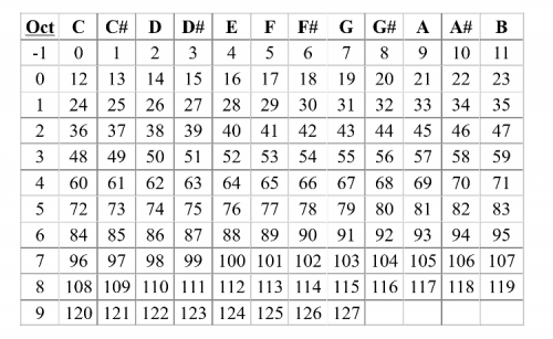
The smoke pin (Arduino pin 7) is the only one set as an output, having to activate the smoke machine relay. The first note in the order of frequency and therefore, if we were on the keyboard of a piano, part n from left, is the one correlated with the digital pin 6 and the most acute is that relating to analog input 4. Then the sequence of the executable notes is Fa#, Sol, Sol#, La, La#, Si, Do, Do#, Re and Re# of the upper octave; if you want to know the correspondence with all the notes executable by the synthesizer integrated into the VS1053B consult Table 1.
Table 1.

Whenever Arduino detects the high logic level on one of the aforementioned lines, it constructs the serial coma n do string of the content synthesizer in VS1053B and sends it to the integrated, which produces the desire led to note ta, with the adjuster (instrument) set in the command itself; in our case the register is fixed in the sketch and is the same for all 10 notes. The instrument reproduced is the 9 of the bank GM1 (Celesta) as shown in Table 2.
Table 2
As far as the smoke machine is concerned, we have modified one of those available on the website (code HQSM10001) connecting in parallel to the smoke jet control button the exchange of a relay on the breakout board, driven by Arduino’s digital pin 7. The output activates (leads to a high logic level) for 400 ms and is then inhibited for 10 seconds, so as to avoid saturating the environment if notes are played continuously.
Times can be changed at will from the sketch. The relay module is of the 1-channel type with TTL command and is the REL AY1CH.
The wiring diagram shown in these pages explains well how the circuit elements must be interconnected.
Regarding the format of the commands from Arduino to the VS1053B, the synthesizer setting string is of this type:
- 0x51: set time
- 0x01: master volume
- 0x80: note off
- 0x90: note on
- 0xc0: program
- 0xe0: pitch wheel
- 0xb0: parameter channel message
- 0x00: bank select (0 is default, 0x78 and 0x7f is drums, 0x79 melodic)
- 0x06: RPN MSB: 0 = bend range,
2 = coarse tune
- 0x07: channel volume
- 0x0a: pan control
- 0x0b: expression (changes volume)
- 0x0c: effect control 1 (sets global reverb decay)
- 0x26: RPN LSB: 0 = bend range
- 0x40: hold1
- 0x42: supported
- 0x5b effects level (channel reverb level)
- 0x62.0x63,0x64,0x65: NRPN and RPN selects
- 0x78: all sound off
- 0x79: reset all controllers
- 0x7b, 0x7c, 0x7d: all notes off
The parameters allow to establish the operation of the synthesizer, that is to say, the instrument (register) to be played and which bank, the possible application of effects such as sustain, the range of the pitch bend if used, etc.
Finally, it is worth highlighting a particularity of the VS1053B, concerning the headphone output stage, in which a parameterization of the audio processing is implemented in four selectable modes; all with the aim of restoring the spatiality that is typically not obtained when listening through headphones.
The four applicable modes are:
- Off: no spatial correction, useful if you listen to the audio in the speaker, since the sound in the surrounding space acquires spatiality of its own; this mode also applies to listen with headphones if the audio to be reproduced derives not from the synthesizer but from the decoder and already contains a binaural preprocessing;
- minimal: designed for headphones listening with few instruments and minimal spatial correction;
- normal: suitable for listening to songs on headphones by moving the perceived audio source in a minimal way from one pavilion to another;
- extreme: suitable for the reproduction of old recordings or dry, or the sound rev or duct is generated MIDI synthesizer.


THE FIRMWARE
Well, let’s complete the description of the laser harp with firmware analysis, downloadable from our website www.elettronicain.it; of it, in Listing 1 we report the part of the sketch that associates the notes with the “strings” to you.
After assigning the I / O pins, set the desired tool with the instruction:
const int INSTRUMENT1 = 9;
Anyone wishing to change the tool can intervene in this area of the code. We then have the portion of the sketch that concerns the setting of the serial communication for the control by Arduino where you can notice that the communication speed is set in 31.250 bps:
#if USE_SERIAL_MIDI
midiSerial.begin (31250); pisello
#endif
And we come to the part of the sketch concerning the command aimed at the generation of the notes, which is the following:
void talkMIDI(byte cmd, byte data1, byte data2) {
#if USE_SPI_MIDI
// Wait for chip to be ready
while (!digitalRead(VS_DREQ))
;
digitalWrite(VS_XDCS, LOW);
#endif

sendMIDI(cmd);
//Some commands only have one data byte.
if( (cmd & 0xF0) <= 0xB0 || (cmd & 0xF0) >= 0xE0) {
sendMIDI(data1);
sendMIDI(data2);
} else {
sendMIDI(data1);
}
#if USE_SPI_MIDI
digitalWrite(VS_XDCS, HIGH);
#endif
}
//Send a MIDI note-on message.
//Like pressing a piano key
//channel ranges from 0-15
void noteOn(byte channel, byte note,
byte attack_velocity) {
talkMIDI( (0x90 | channel), note, attack_velocity);
}
//Send a MIDI note-off message.
//Like releasing a piano key
void noteOff(byte channel, byte note,
byte release_velocity) {
talkMIDI( (0x80 | channel), note, release_velocity);
}
Listing 1
void readTouchInputs ()
{
touchStates [1] =! digitalRead (6);
touchStates [2] =! digitalRead (5);
touchStates [3] =! digitalRead (8);
touchStates [4] =! digitalRead (9);
touchStates [5] =! digitalRead (10);
touchStates [6] =! digitalRead (11);
touchStates [7] =! digitalRead (12);
touchStates [8] =! digitalRead (13);
touchStates [9] =! digitalRead (A5);
touchStates [10] =! digitalRead (A4);

for (int i = 1; i <10; i ++)
{
Serial.print (touchStates [i]);

}
Serial.println ();
}

void Play ()
{
int notes = 30;

for (int i = 1; i <10; i ++)
{
if ((touchStates [i] == 1) && (touchPres [i] == false))
{
noteOn (0, notes, 127);
touchPres [i] = true;
// I pressed a chord
if (fumoinib == 0) {
timefumoon = millis ();
fumoinib = 1;
}

}
if ((touchStates [i] == 0) && (touchPres [i] == true))
{
noteOff (0, notes, 127);
touchPres [i] = false;
}
notes ++;
}
delay (100);
}
The commands, as you can see, set the note, the register, the time, the attack and decay modes (sound progression and decay) and so on, then sending the corresponding command string to MIDI.
Regarding the control of the smoke machine, the parameters are as follows:
unsigned long timefumoon = 0;
int timespruzzo = 400;
int timefumoinib = 10000;
boolean fumoinib = 0;
unsigned long timestartinib = 0;
Here we see that the command to the relay that closes the short-circuit in the machine control button 0.4 seconds, followed by an inhibition time of 10 seconds (all times are expressed in milliseconds).
The part of the code contained in Listing 1 sees the function void readTouchInputs () with the variables associated with the 10 sensors: when a touchStates passes from 0 to 1 a for loop is started which produces the printing on a serial of the note played, for debugging purposes. The void Play () function follows in which a for loop executes the note associated with touchStates, starting with 30, which is the most severe; for each touchStates that changes state, it adds 1 note, so if the switching parameter is touchStates [5] the note parameter is 30 + 4, then note 34 is executed. Of course, those who feel it can change the various parameters in order to deactivate the command of the smoke machine (it is enough to set zero int intro) personalize the notes and, if desired, modify the sound of the instrument.
Well, having said that we have concluded: we can only wish you good luck and above all good fun with your digital harp with which you will be amazed at who will see it played.
Components List:
R1: 1 Mohm (0603)
R2 ÷ R5: 100 kohm (0603)
R6, R7: 22 ohm (0603)
R8: 1 kohm (0603)
R9: 22 ohm (0603)
R10 ÷ R12: 100 kohm (0603)
R13, R14: 1 kohm (0603)
C1 ÷ C5: 100 nF ceramic (0603)
C6: 100 µF 6.3 VL electrolytic (Ø 4mm)
C7, C8: 22 pF ceramic (0603)
C9: 1 µF ceramic (0603)
C10, C11: 10 nF ceramic (0603)
C12: 47 nF ceramic (0603)
C13: 100 µF 6.3 VL electrolytic (Ø 4mm)
RTD: Microswitch
U1: VS1053B
U2: MIC5504-1.8YM5-TR
U3: MIC5504-3.3YM5-TR
U4: Amplifier module PAM8403
SPK: Jack 3.5mm jack
Q1: 12.288 MHz quartz
Various:
- 2-way clamp 5mm pitch (2 pcs.)
- Pin Strip Arduino 6 way
- Pin Strip Arduino 8 way (2 pcs.)
- Pin Strip Arduino 10 way
- Pin Strip Arduino 2×3 way
- Printed circuit S1414 (69×55 mm)

FROM OPENSTORE
Plexiglass parts for LASER HARP

Related Posts


)
-
 Arduino ISP (In System Programming) and stand-alone circuits
We use an Arduino to program other ATmega without...
- Posted 12 years ago
-

-

-
 GSM GPS shield for Arduino
Shield for Arduino designed and based on the module...
- Posted 12 years ago
-
 Small Breakout for SIM900 GSM Module
Some post ago we presented a PCB to mount...
- Posted 13 years ago
-
 Join Maker Faire Rome 2024: Innovation Unleashed at Gazometro Ostiense | Calls Now Open!
All Calls Now Open for Maker Faire Rome 2024...
- Posted 2 weeks ago
-
 Building a 3D Digital Clock with Arduino
Project to create a digital clock consisting...
- Posted 4 months ago
-
 Acoustic amplifier – in DIY Kit
This kit creates a microphone amplifier with an output...
- Posted 5 months ago
-
 Creating a controller for Minecraft with realistic body movements using Arduino
Project of a controller that maps body movements...
- Posted 5 months ago
-
