- How to Adjust X and Y Axis Scale in Arduino Serial Plotter (No Extra Software Needed)Posted 7 months ago
- Elettronici Entusiasti: Inspiring Makers at Maker Faire Rome 2024Posted 7 months ago
- makeITcircular 2024 content launched – Part of Maker Faire Rome 2024Posted 9 months ago
- Application For Maker Faire Rome 2024: Deadline June 20thPosted 11 months ago
- Building a 3D Digital Clock with ArduinoPosted 1 year ago
- Creating a controller for Minecraft with realistic body movements using ArduinoPosted 1 year ago
- Snowflake with ArduinoPosted 1 year ago
- Holographic Christmas TreePosted 1 year ago
- Segstick: Build Your Own Self-Balancing Vehicle in Just 2 Days with ArduinoPosted 1 year ago
- ZSWatch: An Open-Source Smartwatch Project Based on the Zephyr Operating SystemPosted 1 year ago
The 3DRAG CHOCO (Chocolate 3d printer) Cooling system explained
The best result when printing chocolate objects is obtained by cooling quickly the deposited layers, by means of a jet of cold air; here is the device that allows you to do so.
Aside from maintaining the chocolate temperature below the specific threshold (necessary to keep the tempering), to get fast and not deformed prints we must face the cooling time problem. In fact, if you lay down a new layer of melted chocolate on an underlying layer not yet solidified, this can deform the object you are printing. Therefore, the new layer must be deposed only when the underlying one is cold enough to withstand the weight of the new layer above and to dissipate the heat supplied by the melted chocolate.
By working with a relatively small amount of chocolate as the one contained in a needle with a 0.9 mm internal diameter (the one adopted in our tests with the 3Drag Choco) you can go pretty fast. In any case, every printer and every printed object will have its own printing speed and cooling time and, obviously, each printer model (Repetier-Host, Cura etc.) will need its own settings functions and commands to be set properly.
We decided to use Peltier elements, to make a static and compact cooling system that generates a cold air stream blown by a fan towards the chocolate deposit plate. This solution has proved to be the best, although we had to face few problems: despite the small blower size, the stream could invests the nozzle cooling it down enough to solidify the chocolate, blocking the deposition process. The problem was solved by channeling the cold air stream just on the fused chocolate, thanks to a careful vent design that focuses cold air only where needed.
In this article, we describe the rapid cooling system, essential when printing fast but useful at lower printing speed too.
The cooler
This “machine” is both a refrigeration system and a cold air conveyor; the cooling system unit is based on six 12V – 51 W Peltier cells, equipped with heat sinks on the cold side and water cooled on the hot side. Over the cold side heat sink, a fan blows ambient air through a conduct. The cooled air is channeled through a special vent directly to the chocolate deposition plate (i.e. under the extruder nozzle).
We opted for the Peltier cells because, although they have not a great efficiency, they allow us to design and make a solid-state cooling system, compact sized and easily managed by an electronic controller board.
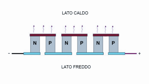
To understand how the system works, we need to explain how the Peltier cells work. These devices are based on the Seebeck effect, which occurs in the junctions between two different metals with different atomic structure; without a pure Physics explanation, we know that the different distribution of valence electrons in different metals causes, when the two are placed in contact, a potential difference.
This voltage is very small (in order of mV) and varies in function of the temperature that the junction is subjected to: it grows with temperature increase and decreases with decreasing temperature. This dependence is explained by the fact that heating increases atoms thermal agitation and so does the potential possessed by the electrons.
Layering junctions between two different metals arranged alternately (I.e. a metal between two slices of a different one) makes the so-called “thermopile”: when heating an end and cooling the other, you can generate a potential difference proportional to the temperature gradient and, closing the thermopile terminals on a load, you have an electrical current flowing.
The thermopile can also work in reverse: fed with an electric current, a junction gets heated and the other is cooled; this phenomenon is the Peltier effect, and explains the Peltier cell principle.
The cells can be constructed using metals, but the high thermal conductivity of such materials would lead to having small temperature differences between the hot and cold sides; for this reason semiconductors materials, having a much greater thermal resistance that better isolates the two junctions and increases the thermal jump, are preferred when building a Peltier cell.
The cell cooling capacity is always less than the electric power absorbed, because an important amount of energy is dissipated as heat; for this the Peltier cells are convenient only where the low energy performance is less important respect to advantages like compactness and fast required temperature reach.
That said, let’s see how the cooler is structured.
System layout
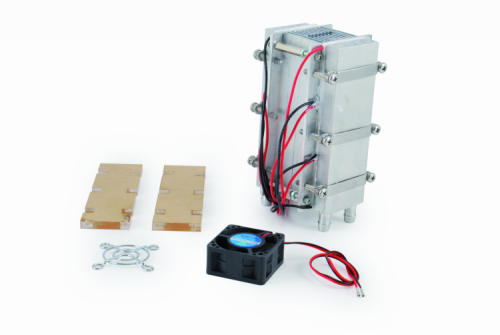
The refrigerating unit is made by two finned heat sinks on one side and plain on the other. The two heat sinks are laid face-to-face and enclosed laterally to be air-sealed (preventing fresh air leaks). On the flat parts, are mounted six 51W Peltier cells, connected in series as shown in the diagram in these pages. The two blocks of three cells are interconnected in parallel, so that we can power the device with a 36Vdc power supply.
We opted for the series-parallel connection, as it is a good solution to use a commonly available on the market 36V power supply, with a current that is not too high limiting thus the power leakage due to cable voltage drop. The three cells in series on each side require 36V (each cell needs 12V) and the two groups are fed in parallel with this voltage. Each row absorbs little more than 4 Amperes, and then 9.6 Amperes provided by our 36V power supply are enough for the whole system.
The Peltier cells cold side is coupled to the aluminum heat sink flat side by using metal screw clamps. The hot sides are coupled to two liquid cooling aluminum waterblocks: the liquid cooling is really efficient and we need it since the more heat we dissipate, the lower temperature we can reach on the cold side.
Each cooling coil is actually a parallelepiped with long faces flat and smoothed so to adhere perfectly to the Peltier cells heat exchanging surfaces. Two tubular fittings with conical arrowhead to lock rubber hoses are used for the hydraulic circuit.
To facilitate the heat exchange, it is better to use a thermal grease (as the one commonly used between CPUs and heat sinks) between the cooling coil and the Peltier cell.
In our design, since this choice does not intriduce particular problems but simplifies the connections, we connected the cooling coils hydraulically and thermally in series: one receives the incoming rubber pipe from the air/water intercooler and the first waterblock outgoing pipe is connected to the second cooling coil. The latter outgoing hose returns to the air/water intercooler.
Two independent bodies connected in series make this intercooler: a pipe connects the upper end of the lower body with the lower part of the upper; the rubber pipes connected to the intercooler’s in/outgoing fittings will be connected to the cooling coils free ends.
This hydraulic series circuit has the main drawback that the second cooling coils receives a liquid already warmed up by the first heat sink, but on the other hands helps us preventing air bubbles in the circuit, a common problem with parallel connected circuits.
A 12V 120×120 mm electric fan, enough to dissipate heat even in summer, cools each one of the intercooler two bodies.
Note that the water / air exchanger can also be single body. At the lower water inlet we have to mount a 12V electric pump, like the MINIPOMPA12V available on Futura Elettronica Shop (www.futurashop.it); it is a small and very light device, capable of a flow rate of 240 liters / hour, to push water to a height of 3 meters and protected, on the electrical side, up to IP68. The absorption is 400 mA.
The aluminum heat sinks block and the Peltier cells should be laterally covered (but also completely if you prefer) with insulating material, to waste less heat as possible.
According to the proper system operations, the described body should be arranged vertically, with 40×40 mm fan on top aspiring the cooled air and sending it to the plastic conveyor. This conveyor is connected through a plastic hose to the special conduct put near the printing head of our Choco 3Drag.
The vertical mounting setup helps avoiding the condensing air humidity to be sprayed directly to the deposited chocolate: the water condensed on the intercooler (during the de-freezing process, that is managed by the controller and that we’ll describe in a while) will drop down, saving the fan (that is mounted on the upper end) and the printing plate.
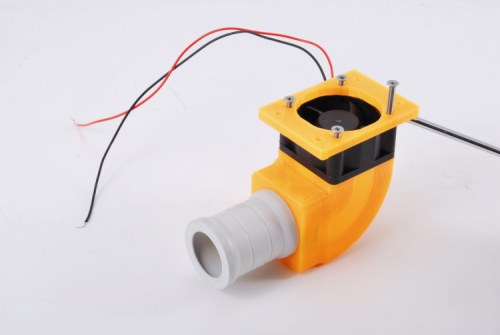
The fan blows the cooling air into a 3D printable plastic conveyor (print it with your 3Drag using these STL files); the conveyor is assembled on top of the 40x40mm fan with a plastic adapter (also printable in PLA with 3Drag starting from STL we provide) and ends with a tube coupling (like the one used for electrical systems) inserted and screwed (with its appropriate ring) in the upper plate, which is already drilled for the purpose. The 25mm junction, watertight (IP66) allows to apply the 25 mm diameter corrugated tube without flow losses.
The conveyor, complete with fan and connection is visible in figure.
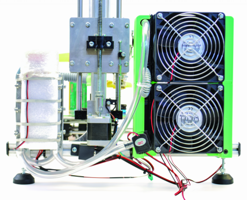
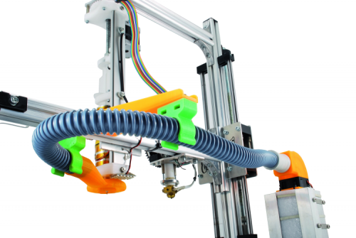
The cooler and the conveyor system is, fully assembled, as shown in figure . Since all the fans are 12 volts models, they are connected in parallel to a DC / DC converter that provides this output voltage. The converter is powered by the same 15 V DC power supply that powers the electronic control system.
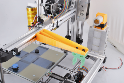
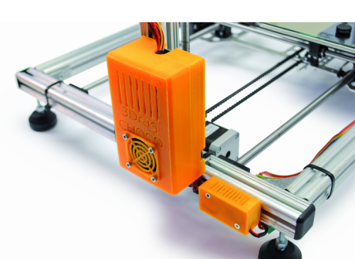
The corrugated tube that brings cold air directly to the extruder is long and not much flexible; since it must be bended, it needs to be supported by a dedicated arm mounted on the 3Drag horizontal profile (the same that holds the print head). Both these parts are printed with the 3Drag, starting from .STL file we provide (PLA is fine).
The arm is fixed to the printing head supporting aluminum bar with square nuts slid into the profile, then tighten with the bolts provided. The clip is screwed to the opposite arm end with 5MA bolts and nuts (there are apposite slots in the clip). The set is displayed in figure.
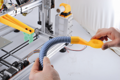
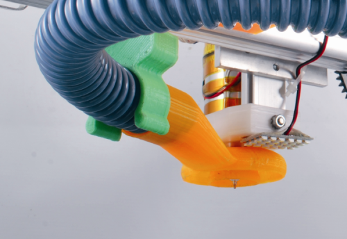
Made the mechanical assembly, we must connect one end of the corrugated tube to the special cold air vent, which is a sleeve (also printable in PLA with 3Drag) terminating with an open ring (“donut”) on the bottom to blow directly onto the melted chocolate.
This positioning arrangement, combined with the fact that the nozzle can be mounted in the inner hole of the donut, thus surrounding the printing head, helps us avoiding to insulate the outside of the latter. Once applied the corrugated tube other end to the conveyor located on the chiller group, the machine will be as shown in figure.
The control unit
Let us now focus on the electronic control unit, which drives the cooler. It is the same 3Drag v1.2 printer controller, which uses the output for the heated plate (that for the Choco printing is not needed, since we need to cool the area…) to supply, through a 12V-30A relay, the Peltier cells circuit. We also use the FAN output (to be managed by the appropriate command in the printing client software) to control the 40x40mm fan. Of course, it is needed to upload the proper firmware to the ATmega2560 to have this control activated.
The firmware does not manages the cold air temperature, but, to prevent the icing of the condensing air humidity that can obstruct the duct between the heat sinks, we need to periodically switch the Peltier cells off. To do this, we can use the heated plate control available on Repetier-Host or on Cura printers for example. The ice on the heat sinks will melt and drop out on the radiators bottom.
The shut-off period shall be chosen according to your experience and to the air humidity percentage; clearly at the beginning you have to do some testing to take confidence.
Since the firmware is written to read the heating plate temperature through a NTC, we need to “deceive” the controller by connecting a 120KOhm resistance (0,25W) to the thermistor dedicated pins.
The printer connections scheme is the 3Drag original one, and since this project is supposed to be made on an already assembled and working printer, we will not repeat it here. What you need is the cooling system connection as we’ve already shown before. For the controller board and the DC/DC converter we imagine PLA boxes, printable with 3Drag (you can download the STL files).
Having closed the controller in a box, we have designed openings needed for the ventilation required by the driver modules, as well as a 12V 40×40 mm optional fan slot to cool the controller. The two containers are to be secured to one of the side sections of the printer with screws provided with spacers and nuts.
From openstore






9 Comments