- How to Adjust X and Y Axis Scale in Arduino Serial Plotter (No Extra Software Needed)Posted 4 months ago
- Elettronici Entusiasti: Inspiring Makers at Maker Faire Rome 2024Posted 4 months ago
- makeITcircular 2024 content launched – Part of Maker Faire Rome 2024Posted 6 months ago
- Application For Maker Faire Rome 2024: Deadline June 20thPosted 8 months ago
- Building a 3D Digital Clock with ArduinoPosted 1 year ago
- Creating a controller for Minecraft with realistic body movements using ArduinoPosted 1 year ago
- Snowflake with ArduinoPosted 1 year ago
- Holographic Christmas TreePosted 1 year ago
- Segstick: Build Your Own Self-Balancing Vehicle in Just 2 Days with ArduinoPosted 1 year ago
- ZSWatch: An Open-Source Smartwatch Project Based on the Zephyr Operating SystemPosted 1 year ago
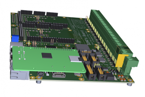
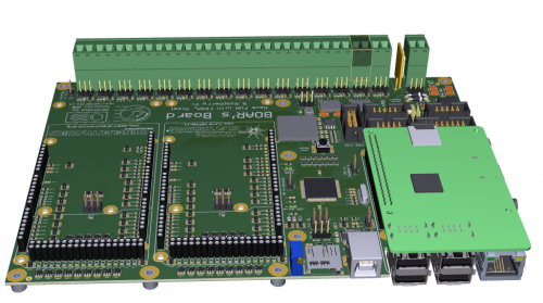
Boar’s Board, something wild is making its way into the world of electronics
This project was born from the idea of designing a board with an FPGA for didactic purposes, something that would allow hobbyists and electronic engineering students to learn how to use this type of programmable devices in a quick and easy way.
Numerous boards of this kind are already present on the market, so it seemed futile to replicate what has already been successfully implemented, therefore we decided to take a different path and avoid designing the usual FPGA board with a single function. We started thinking about something more original, which would combine different functions in a single board and at the same time be practical, easy and fun to use. Hence the concept of a board that integrates the world of hardware, firmware and operative systems: the Boar’s Board!
Programmable logics that can integrate these three worlds in a single silicon chip are already available, but the big issue with using these components is that they require from the user a great deal of competence in different fields. Long learning processes and many specific courses are needed before getting a minimum result on any of these devices, even for the simple action of getting an LED to blink.
In the companies where these devices are used, a project is never developed just by one person; on the contrary, it’s always implemented by a team of project managers and engineers, each with their own specific competences (which may span from high-level programming languages to VHDL, C, and Assembler), often with the need to develop also kernel-level specific drivers.
Burdening a newbie or a student with such a workload is definitely not an ideal scenario. We have therefore decided to avoid a totally integrated FPGA-Linux device, proceeding on an alternative path. When we designed our board we set some key points we wanted to stick to in order to obtain a good final result in spite of all the inevitable compromises we had to deal with.
Specifically, this board was designed to:
1) be useful both for didactic purposes and for generic use;
2) be simple and intuitive;
3) be used also for small series of prototypes;
4) integrate the use of operative systems with microcontrollers and FPGAs;
5) allow people to use it even if they are not knowledgeable of all these three worlds;
6) be used only in part (just the microcontroller, just the FPGA, just the S.O., or all of them together);
7) make the most of the well-known software toolchains and S.O. platforms used by amateurs and professionals;
8) use the existing hardware expansions as much as possible, without reinventing what already exists;
9) offer good computational power, so that the platform can be used also for other purposes rather than just ‘playing’ with it;
10) include some technical improvements not normally found in standard starter kits and amateur-aimed boards;
11) take care of all the mechanical and technical aspects of the design, in order to be used both as a proof-of-concept and in mini production series if needed.
Designing a board which would take care of all these aspects has been a hard task full of planning and compromise. It wasn’t possible to satisfy everyone, but we hope we have met most people’s needs as much as possible.
Main design choices:
Main components
The Raspberry Pi is quite popular and available in several different distributions, with operating systems that range from Linux to Windows 10, therefore we’ve chosen to place a socket on our board that can mount the Raspberry Pi in its latest and most powerful hardware configuration.
As for the microcontroller, we have chosen to use the popular ATMega2560 by Atmel, both for its user-friendliness and its huge software library, available via the Arduino toolchain.
As far as the FPGA is concerned, we have decided on a robust Altera device with good computational power and a high number of I/Os, which can be useful also for complex projects.
Architecture
In order to maximise the use of the main components, we have decided to connect the whole microcontroller BUS to the FPGA, so as to be able to get direct access to the internal FPGA hardware acceleration registers. This allows for maximum throughput and a very flexible integration between hardware and software.
All the remaining microcontroller I/Os have been placed on specific connectors, allowing to connect other expansions, like keyboard, LCD display, and so on. In particular, one of these connectors has been mapped for practical reasons, providing a pin-to-pin connection with many common LCDs used by the Arduino community.
Due to the high number of digital I/Os available on the board, we have decided to keep all the 16 analog inputs of the microcontroller free for analog use. All of them have their own protections and a double, full-scale selector (5-10V).
The Atmel processor is supplied from the 5V power supply, so that it can work at 16MHz. Since the FPGA I/Os work only at 3.3V, an adaptation circuitry has been added. Anyway, if the user wants to switch the processor to 3.3V, a specific jumper allows voltage change.
In many applications, like for example 3D printers, a microSD is often used. Since the board can also work without the Raspberry Pi, in order to give the system more flexibility, this peripheral has been maintained and connected to the 8-Bit processor.
All the I/Os of the Raspberry Pi have been connected to the FPGA to maximise board flexibility and allow the use of all the peripherals made available by the operative system.
This architecture provides high computational power, so we have decided to provide the proportionate number of 154 digital I/Os, which we have made available on the mechanically-compatible Arduino Mega sockets.
Our FPGA works at a maximum I/O voltage of 3.3V. In order to maximise the compatibility with the Arduino shields (which typically work at 5V), each of these lines has its own clamping protection circuit.
Available power supplies:
-
via USB port,
-
external 5V power supply,
-
external 8-30V power supply.
These three options add flexibility of use. For example, when used for FPGA teaching purposes, no external power supply is needed, and the board can take the power supply directly from the PC it is connected to. When used in standalone mode, instead, the wide input voltage range simplifies its use.
Mechanical aspects
Although this is mainly a didactic board, we have tried to keep it as close as possible to the industrial standards. In this way, beside an initial phase of development, experimenting and proof-of-concept, the board can also be used to implement small production batches without the need for an expensive process of specific design and industrialization.
The type of connectors and their position on the board follow a specific and strategic placement logic. Since the board may be boxed and used like a mini-PC, on the rear end of it you can find all the external connections, i.e. the Raspberry USBs and Ethernet port, the USB port connected to the FPGA and the microcontroller, the microSD, and the contrast control in case you want to connect it to an LCD display. On the left side we can find the HDMI port and the audio jack socket. For practical reasons, the power supply, the generic I/Os of the microcontroller and all the analog inputs are located on the front of the board.
Given the high number of connections, we have chosen to fit the board with pluggable connectors. They are a bit more expensive than soldered ones, but they are much more practical during the development process, when you often need to plug and unplug boards.
Since we wanted to use something that is already widely available on the hobbystic market, instead of using proprietary connectors, for the FPGA I/Os we have decided to keep the Arduino-Mega connections layout style. This allows the use of many existing boards until our new expansions become available.
Other aspects
We have designed this architecture trying to find a balance between simplicity and potential of the board, and putting ourselves in the shoes of a hobbyist or a student.
At the beginning, using a powerful and complex single-chip solution (FPGA – processor – Linux) is very complicated and time consuming, and frustrated newbies often abandon these chipsets before getting any result out of them. Thanks to our approach, instead, people can quickly and easily start working with the board and acquire competences step by step. They can use existing libraries as a starting point, modifying them according to their needs and getting tangible results very quickly. Moreover, being able to concentrate on the aspects they know best (FPGA-FIRMWARE-SOFTWARE), the learning process will be smoother and easier, encouraging them to go on.
In the near future, we will release specific open source libraries for the FPGA, the processor and the O.S., providing peripheral resources like smart stepper controllers, PWMs, PPMs, IICs, and more.
Using this strategy, students who have some knowledge of Linux could use the available hardware resources without necessarily knowing anything about Arduino or FPGAs. They could concentrate on what’s more familiar to them and still exploit the full potential of the board. In the same way, students who prefer to use microcontrollers can concentrate on developing their own applications without having to know how to program FPGAs, but using their peripherals anyway. Students who want to work only with FPGAs, instead, can simply ignore the rest of the board and concentrate on their task.
For those who want to fully exploit the potentials of these three worlds, the learning time needed to get appreciable results is quite short. In this case, the typical trial and error process is significantly simplified as compared to working with complex single-chip solutions.
The name
The electronics market has recently been invaded by ‘fruity’ boards, so we have preferred to take a different path. For our solution we have chosen the boar, a strong and powerful animal who lives in total freedom, enjoying his environment and feeding on any available food, be they FPGAs, microcontrollers, or operating systems!
Conclusions
Despite our efforts, we are aware that we may not have satisfied everybody’s wishlist with a single product. Nevertheless, we hope we have been able to meet as many of your needs as possible. Our hope is that this board will be useful to many of you, helping you deepen your knowledge of the fabulous world of electronics. Sometimes, even the most complex projects can successfully be implemented when taken in small steps, and the most simple things can lead you to great achievements.
Anticipations
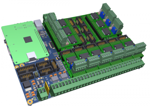
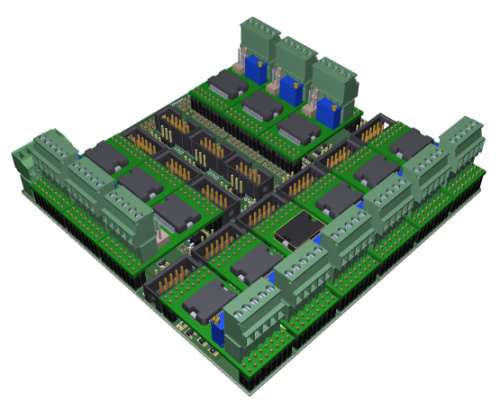
Last but not least, an anticipation on the first ‘piglet’ that mummy Boar is soon going to give birth to. We are talking about an expansion board, specifically designed for those who want to experiment with robotics, 3D printers, or small CNC machines.
Main features:
12-axes smart stepper-motor controller with current ranging from 3 to 10A per axis;
12-axes RC-servo driver for brushless motor control or small actuator movements;
12 high-power outputs to drive heaters or on/off mechanical actuators;
24 digital inputs with pull-ups to manage end strokes or other functions.
Both the motherboard (‘Boar’s Board’) and the multi-axes expansion board (‘Boar’s Piglet 01’) have already been designed, and we are currently waiting for the first few prototypes. While we debug the system, we would like to get some feedback from you on how much interest there could be for such a product, so that we can decide how many boards to put in production for the first batch.
Production costs may vary significantly depending on quantities, so we hope many of you are interested in buying this platform. The higher the quantities, the lower the price.
We will keep you posted on the boards’ availability and prices. One of the options we are thinking about is putting this project on Kickstarter, in order to test the market potential and go into full production as soon as possible.
We hope you like our idea enough to support us, and hope our products will help you enjoy the fascinating world of electronics even more.
Lorenzo Bolla
IW2EAX


2 Comments