- How to Adjust X and Y Axis Scale in Arduino Serial Plotter (No Extra Software Needed)Posted 7 months ago
- Elettronici Entusiasti: Inspiring Makers at Maker Faire Rome 2024Posted 7 months ago
- makeITcircular 2024 content launched – Part of Maker Faire Rome 2024Posted 9 months ago
- Application For Maker Faire Rome 2024: Deadline June 20thPosted 11 months ago
- Building a 3D Digital Clock with ArduinoPosted 1 year ago
- Creating a controller for Minecraft with realistic body movements using ArduinoPosted 1 year ago
- Snowflake with ArduinoPosted 1 year ago
- Holographic Christmas TreePosted 1 year ago
- Segstick: Build Your Own Self-Balancing Vehicle in Just 2 Days with ArduinoPosted 1 year ago
- ZSWatch: An Open-Source Smartwatch Project Based on the Zephyr Operating SystemPosted 1 year ago
Big Spectrum Analyzer with Arduino
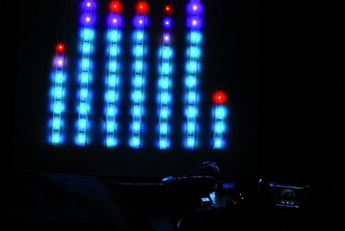
Let’s put together a pixel strip with an HL1606, an Arduino UNO and the Spectrum Shield to build a seven bands “large” Spectrum Analyzer of simple construction.
[iframe_loader src=”http://www.youtube.com/embed/bVw02EXmmdo?hl=it&fs=1″ height=”349″ width=”425″ ]
The components
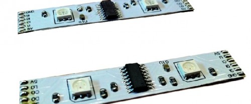
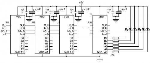
The Strip used uses the HL1606 controller to allow direct management of each of the LEDs. The chip runs two RGB groups and has 4-pin for input/output. The serial communication protocol allows input to output passage whenever the chip receives new data. Data move from one module to another thanks to a clock provided on the control line. Every strip can be composed of a variable number of modules up to a theoretical maximum determined only by the speed with which we want to change the LEDs status.
Each chip continues in the pass through without displaying received data, until the latch pin (L-s) status changes . Then it writes the value from it’s communication registry in registry piloting the six channels.
For the HL1606, data is a bitmap (a one byte word for each RGB LEDS) corresponding to each of the three LEDs, managed according to a truth table having two bits for each LED. The chip does not have autonomous blending management (PWM), but it uses a SI line to give the automatic blending frequency, which is available as a stand-alone function.
The second key component of this project is a MSGEQ7 chip. The chip is designed for seven-band equalizers, for displaying the peak level of each of the bands. With just eight pins it has a “clever” mechanism: this chip offers, on a single pin, a voltage level that is equal to the peak level of one of the seven frequencies managed.
The transition from one frequency to another is managed via a strobe pin, which increments a multiplexer including all seven Bandpass Filters with peak detectors.
Basically, on the same pin on can be read a sequence the seven peak levels for the seven bands centered on 63, 160, 400, 1,000, 2,500, 6,250 and 16,000 Hz.
If we add an Arduino UNO, we have everything we need to read the seven values on different frequency bands, and create a representation of the same on a series of bars, in fact our giant Spectrum analyzer.
Creating seven bands without cutting the led strip
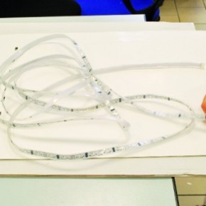
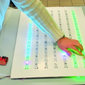
The flexible nature of the strip we’ve chosen allows us to model it as we prefer: in our case, we get seven bands bars simply by folding the strip to form a coil. Between a bar and the other we’ll leave three LEDs (to avoid excessive stress on the Strip).
The height of the bar depends on the total length; firmware adjusts it, using only the LEDs needed. In our case we are using a standard 5 meters strip and 160 LED: we will therefore have six curves by three LEDs (18 LEDs are not used) to have seven 20 LED bars each. Two diodes remain unused at the end of the Strip, that is considered in counts.
With this arrangement, even bars work in a verse and odd ones in another: this is managed by the firmware.
The Spectrum Shield
The peculiar MSGEQ7 chip has attracted the attention of several companies. Bliptronics and Sparkfun, have therefore carried out a Spectrum Shield: a shield for Arduino, mounting two chips and two stereo jacks: one for receiving the input signal and another for the pass through output.
The two MSGEQ7 handle the stereo signal channels, read from the analog A0 and A1 pin by the Arduino. The Reset and the Strobe of MSGEQ7 are, respectively, connected to D5 and D4 of Arduino.
The shield has a button to reset the Arduino connected through lateral connectors, while a large Breadboard area allows you to add any accessory components.
You don’t need a library specific for this shield: acting on Reset and Strobe you have the sequence of levels on Arduino analog inputs in an endless loop. A cycle that feeds a seven values vector you can then pass the data to the graphic representation.
How to handle the Strip
To represent the light bars on the strip, we use a ready-made specific HL1606 library. This library can manage a strip of arbitrary length, giving you control over the single LED. For performance reasons, the simplest version does not handle the PWM for the blending, restricting the feature to seven representable colors.
In addition to this library, the code requires SPI features handled by the standard “wire” library that will also set in includes.
Wiring
From an electrical point of view, the Strip needs a 5 V power supply with a current of approx. 2 A, which must be taken from an external power supply. Arduino 5 V are not enough.
Of the other four signals coming from the strip, just DI, LI and CI , and interesting for us. You’ll find explanations regarding the use of the S signal in the box on the previous pages. The connections to the Arduino i/o for these three pin are the following: D = D11; L = D12; C = D13.
The Spectrum Shield connects to the following lines of Arduino: Reset = D5; Strobe = D4; Left = A0; Right = A1.
The program
// Vu meter By Boris Landoni
// www.open-electronics.org

#include "HL1606strip.h"
#include

// use -any- 3 pins!
#define STRIP_D 11
#define STRIP_C 13
#define STRIP_L 12

// Pin S is not really used in this demo since it doesnt use the built in PWM fade
// The last argument is the number of LEDs in the strip. Each chip has 2 LEDs, and the number
// of chips/LEDs per meter varies so make sure to count them! if you have the wrong number
// the strip will act a little strangely, with the end pixels not showing up the way you like
HL1606strip strip = HL1606strip(STRIP_D, STRIP_L, STRIP_C, 160);

//For spectrum analyzer shield, these three pins are used.
//You can move pinds 4 and 5, but you must cut the trace on the shield and re-route from the 2 jumpers.
int spectrumReset=5;
int spectrumStrobe=4;
int spectrumAnalog=0;  //0 for left channel, 1 for right.

int MyDisplay[25];

// Spectrum analyzer read values will be kept here.
int Spectrum[7];
int lung=19;  //lunghezza della barra
int space=4;  //Spazio tra una banda e l'altra

//la barra viene divisa in tre parti
int colorbar1_3=GREEN;      //colore prima parte
int colorbar2_3=YELLOW;      //colore seconda parte
int colorbar3_3=RED;      //colore terza parte
int colorstart=TEAL;      //colore del puntino di parteza della barra
int colorend=RED;        //colore del puntino che segna la fine della banda
int sect1=7;              //punto di fine primo settore e inizio secondo settore
int sect2=14;            //punto di fine secondo settore e inizio terzo settore
boolean bar=1;            //se 1 viene disegnata la barra, se 0 il livello viene visualizzato solo con un puntino (se 0 la variabile pointend deve essere a 1)
boolean pointend=0;      //se 0 non viene visualizzato il puntino a fine barra
boolean pointstart=0;    //se 0 non viene visualizzato il puntino al'inizio della barra
unsigned int  Divisor = 70, ChangeTimer=0; //, ReminderDivisor,

void setup() {
  byte Counter;
  Serial.begin(9600);
  Serial.println("hello!");

  //Setup pins to drive the spectrum analyzer.
  pinMode(spectrumReset, OUTPUT);
  pinMode(spectrumStrobe, OUTPUT);

  //Init spectrum analyzer
  digitalWrite(spectrumStrobe,LOW);
    delay(1);
  digitalWrite(spectrumReset,HIGH);
    delay(1);
  digitalWrite(spectrumStrobe,HIGH);
    delay(1);
  digitalWrite(spectrumStrobe,LOW);
    delay(1);
  digitalWrite(spectrumReset,LOW);
    delay(5);
  // Reading the analyzer now will read the lowest frequency.

stripOff();

}

void loop() {

  int Counter, Counter2, Counter3;

  showSpectrum();
  delay(15);  //We wait here for a little while until all the values to the LEDs are written out.
              //This is being done in the background by an interrupt.
}

// Read 7 band equalizer.
void readSpectrum()
{
  // Band 0 = Lowest Frequencies.
  byte Band;
  for(Band=0;Band <7; Band++)
  {
    Spectrum[Band] = (analogRead(spectrumAnalog) + analogRead(spectrumAnalog) ) >>1; //Read twice and take the average by dividing by 2
    digitalWrite(spectrumStrobe,HIGH);
    digitalWrite(spectrumStrobe,LOW);
  }
}

void showSpectrum()
{
   readSpectrum();
   byte Band, BarSize, MaxLevel;

   unsigned int works, Remainder;

  MaxLevel = 0;

  for(Band=0;Band<7;Band++)//We only graph the lowest 5 bands here, there is 2 more unused!
  {

     works = Spectrum[Band]/Divisor;	//Bands are read in as 10 bit values. Scale them down to be 0 - 5
     if(works > MaxLevel)  //Check if this value is the largest so far.
       MaxLevel = works;
        colorWipe(Band,works);
  }
 strip.writeStrip();

 // Adjust the Divisor if levels are too high/low.  AGC
  if (MaxLevel >= (lung-1))
  {
    Divisor=Divisor+1;
    ChangeTimer=0;
  }
  else
    if(MaxLevel < (sect2))
    {
      if(Divisor > 50)
        if(ChangeTimer++ > 20)
        {
          Divisor--;
          ChangeTimer=0;
        }
    }
    else
    {
      ChangeTimer=0;
    }
  }

void colorWipe(uint8_t Band, uint8_t works) {
  uint8_t i;
  int inizio=Band*(lung+space);
  int fine  =inizio+lung-1;

  for (i=inizio; i < (fine); i++) {
        strip.setLEDcolor(i, BLACK);
  }
  if (Band==0 || Band==2 || Band==4 || Band==6){

    if (pointstart==0) {
      inizio--;
   }
    else
    {
      strip.setLEDcolor(inizio, colorstart);
    }
    if (bar==1){
      for (i=inizio+1; i < (inizio +works); i++) {
        if ((i-inizio) <=sect1) strip.setLEDcolor(i, colorbar1_3);
        if ((i-inizio) >sect1 &&(i-inizio) <=sect2) strip.setLEDcolor(i, colorbar2_3);
        if ((i-inizio) >sect2 ) strip.setLEDcolor(i, colorbar3_3);
      }
     }
    if (pointend==1) strip.setLEDcolor((inizio +works), colorend);
  }

  else

  {
    if (pointstart==0) {
      fine++;
    }
    else
    {
     strip.setLEDcolor(fine, colorstart);
    }
    if (pointend==1) strip.setLEDcolor((fine-works-1), colorend);
   if (bar==1){
     for (i=(fine-works); i < fine; i++) {
        if ((fine-i) <=sect1) strip.setLEDcolor(i, colorbar1_3);
        if ((fine-i) >sect1 &&(fine-i) <=sect2) strip.setLEDcolor(i, colorbar2_3);
        if ((fine-i) >sect2 ) strip.setLEDcolor(i, colorbar3_3);
      }
    }

  }

}

  // turn everything off (fill with BLACK)
void stripOff(void) {
  // turn all LEDs off!
  for (uint8_t i=0; i < strip.numLEDs(); i++) {
      strip.setLEDcolor(i, BLACK);
  }
  strip.writeStrip();
}
Our sketch consists of the classic parts: includes for libraries, initialization, setup and loop.
The initialization part loads the HL1606 library and the wire standard library. Then defines the connection pins for the strip and the Spectrum Shield.
The software manages the spacing between the bars and their length parametrically (3 and 20 for us). Always parametric is bars color, divided into three parts, with color and length are managed by many parameters. As happens in commercial spectrum analyzers, even our can have the sliding dot indication or variable length bar.
In setup we initialize the serial port, the two control pins of the Spectrum shield are defined as outputs and the Strobe/Reset sequence is performed to bring the chip at the beginning of the reading sequence. The main loop consists of a series of functions where first the spectrum is shown, then the next seven values are read, the reads are compared to the available led number and LEDS status is put in memory. Finally everything is turn off before the next loop start.
Easy!




Pingback: Светомузыка | Pearltrees
Pingback: Светомузыка | Pearltrees