- How to Adjust X and Y Axis Scale in Arduino Serial Plotter (No Extra Software Needed)Posted 4 months ago
- Elettronici Entusiasti: Inspiring Makers at Maker Faire Rome 2024Posted 4 months ago
- makeITcircular 2024 content launched – Part of Maker Faire Rome 2024Posted 6 months ago
- Application For Maker Faire Rome 2024: Deadline June 20thPosted 8 months ago
- Building a 3D Digital Clock with ArduinoPosted 1 year ago
- Creating a controller for Minecraft with realistic body movements using ArduinoPosted 1 year ago
- Snowflake with ArduinoPosted 1 year ago
- Holographic Christmas TreePosted 1 year ago
- Segstick: Build Your Own Self-Balancing Vehicle in Just 2 Days with ArduinoPosted 1 year ago
- ZSWatch: An Open-Source Smartwatch Project Based on the Zephyr Operating SystemPosted 1 year ago
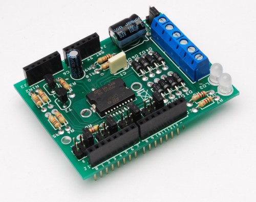
Arduino Motor Shield
We are not the first to make an Motor Shield for Arduino. But could be that we are the first that make a Motor Shield with a minimum of flexibility.
We are studing a WiFi robot with camera controlled by Arduino. The robot will be controlled by browser. But we find a problem with an existing shield: the pin SPI to controll Ethernet shield (that become WiFi shield) are the same of motor shield.
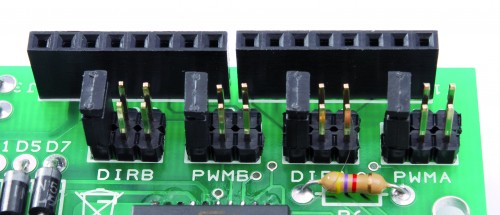
So we reengineered the Motor Shield and we allow to user the choice of what pin use to drive the L298. Infact we provided some jumper to select the pin to use.
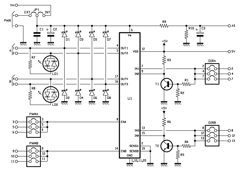
But the schematic is more clear…
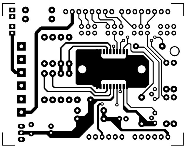
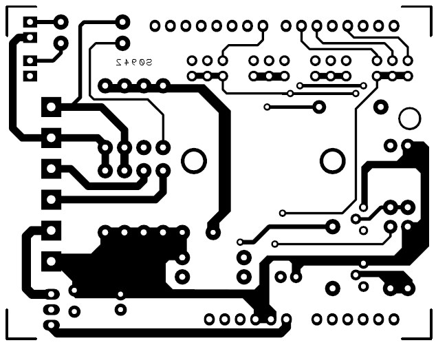
The Motor Shield schematics
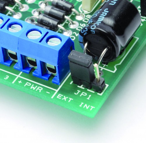
The main power can be selected by a jumper: if the motors work at 12V and the current is less than 1A you can chose the VIN input (INT) and power the Arduino with a 12V, else if the motors work higher than 12V you must chose the EXT input anche connect the power to PWR screw.
The core of the project is a L298 H-Bridge, a motor driver with this caracteristics:
We chose the SMD version of L298 because is also simple to solder, but the profile is lower than the traditional version, so other shield could be mounted without problem.
The main power is transferred to the analog input A5 through a voltage divider (R9 and R10) to reduce the voltage on A5. This can be useful e.g. for all the application that use a battery (like our WiFi robot).
With the jumper DIRA and DIRB the user select the direction of the motor A and B.
The speed is controlled by PWMA and PWMB. All the pins conneted to these jumpers are obviously PWM pins.
The LD1 and LD2 are special leds that light on red or green in function of directions.
With this shield the user can also drive a step motor without problem.
Part list
[code]
R1: 4,7 kohm
R2: 10 kohm
R3: 4,7 kohm
R4: 4,7 kohm
R5: 10 kohm
R6: 4,7 kohm
R7: 1 kohm
R8: 1 kohm
R9: 100 kohm
R10: 10 kohm
C1: 100 nF 100
C2: 100 µF 63 VL
C3: 22 µF 35 VL
U1: L298P
LD1: Led 5 mm R/G (L-57EGW)
LD2: Led 5 mm R/G (L-57EGW)
D1: 1N5819
D2: 1N5819
D3: 1N5819
D4: 1N5819
D5: 1N5819
D6: 1N5819
D7: 1N5819
D8: 1N5819
T1: BC547
T2: BC547
screw 2 via (3 pz.)
Strip male 3 via (9 pz.)
Jumper (5 pz.)
Strip M/F 6 via (2 pz.)
Strip M/F 8 via (2 pz.)
PCB
[/code]
Code
This code originaly is used to drive the Sparkfun’s motor shield.
I modified only the pins used to drive the L298. If you need you can chose other pin with the jumper and modify the sketch.
/*
10-5-10
Pete Dokter
SparkFun Electronics
*/

int pwm_a = 3;  //PWM control for motor outputs 1 and 2 is on digital pin 3 (or 5,6)
int pwm_b = 9;  //PWM control for motor outputs 3 and 4 is on digital pin 9 (or 10,11)
int dir_a = 2;  //direction control for motor outputs 1 and 2 is on digital pin 2 (or 4,7)
int dir_b = 8;  //direction control for motor outputs 3 and 4 is on digital pin 8 (or 12,13)

void setup()
{
  pinMode(pwm_a, OUTPUT);  //Set control pins to be outputs
  pinMode(pwm_b, OUTPUT);
  pinMode(dir_a, OUTPUT);
  pinMode(dir_b, OUTPUT);

  analogWrite(pwm_a, 100);  //set both motors to run at (100/255 = 39)% duty cycle (slow)
  analogWrite(pwm_b, 100);

}

void loop()
{
  digitalWrite(dir_a, LOW);  //Set motor direction, 1 low, 2 high
  digitalWrite(dir_b, LOW);  //Set motor direction, 3 high, 4 low

  delay(1000);

  analogWrite(pwm_a, 255);  //set both motors to run at 100% duty cycle (fast)
  analogWrite(pwm_b, 255);

  delay(1000);

  digitalWrite(dir_a, HIGH);  //Reverse motor direction, 1 high, 2 low
  digitalWrite(dir_b, HIGH);  //Reverse motor direction, 3 low, 4 high

  delay(1000);

  analogWrite(pwm_a, 100);  //set both motors to run at (100/255 = 39)% duty cycle
  analogWrite(pwm_b, 100);

  delay(1000);
}
Design

