- How to Adjust X and Y Axis Scale in Arduino Serial Plotter (No Extra Software Needed)Posted 4 months ago
- Elettronici Entusiasti: Inspiring Makers at Maker Faire Rome 2024Posted 4 months ago
- makeITcircular 2024 content launched – Part of Maker Faire Rome 2024Posted 6 months ago
- Application For Maker Faire Rome 2024: Deadline June 20thPosted 8 months ago
- Building a 3D Digital Clock with ArduinoPosted 1 year ago
- Creating a controller for Minecraft with realistic body movements using ArduinoPosted 1 year ago
- Snowflake with ArduinoPosted 1 year ago
- Holographic Christmas TreePosted 1 year ago
- Segstick: Build Your Own Self-Balancing Vehicle in Just 2 Days with ArduinoPosted 1 year ago
- ZSWatch: An Open-Source Smartwatch Project Based on the Zephyr Operating SystemPosted 1 year ago
An Open Source, hackable Digital Clock
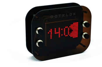
Andrew O’Malley, an amazingly creative maker, created this fanstastic Open Source Arduino-based clock that can display the time in many different ways: if not enough, one can also add his own personal animation.
Andrew’s idea
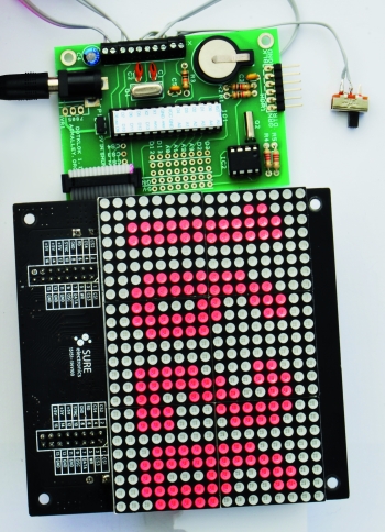
Compared to other clocks based on Arduino, this one has two distinctive features: a single board with the ATmega 328P chip plus the RTC (not a shield) and a led matrix display (16 x 24 pixels) based on Holtek HT1632 chip. The display is already mounted and with a serial interface.
Due to this hardware solution, in which the specialized chips help the Arduino board (tacking care of the complexities of managing a matrix display and monitoring the time), you would think of just few lines of code. It would indeed be so if Andrew O’Malley had not chosen to create a design object: from a simple time display to an opensource system capable of displaying complex animations.
The Schematic
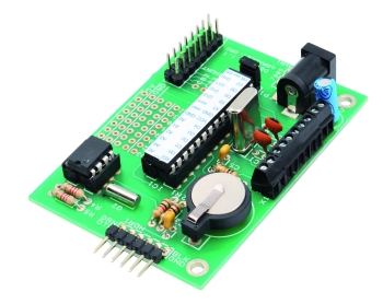
The current hardware version (the 1.1) is published under Creative Commons Attribution-Sharealike (CC BY-SA 3.0) license. This version uses a 28-pin DIL version of the ATmega 328P, the real-time clock from Dallas Semiconductor DS1307, an optional 7805 voltage regulator and two quartzs. The first is 16 MHz and is for the microcontroller; the second is the typical cylindrical quartz for watches, gives 32.768 kHz.
A few other passive components complete the circuit. The lithium backup battery is connected to pin 3 (VBAT) of the RTC.
The power supply of the microcontroller and the display is 5V: with all the LEDs on the display reaches about 200 mA absorption, while the microcontroller takes just a few tens milliamperes. Looking at the scheme, one can see that the typical Arduino pin mapping has been reported on the various connectors following a compatibility logic.
The serial port is connected to pin 2 (RXD) and 3 (TXD) of the microcontroller. The DTR serial port connects to pin 1 (RESET) in order to activate the bootloader when you start programming. The circuit only sports the TTL interface so to connect to a PC to use the Arduino IDE one must use the classic USB / Serial interface. The schema includes a header (HDR1) realized with a 6-pin strip to connect to this interface.
The second connector (HDR2) is instead chosen specifically (16 pins in two rows) to be compatible to that of the LEDs matrix; on this connector we have the connection of the pins D9, D10 and D11 (corresponding to 15, 16 and 17 on the micro) used for communication with the HT1632 chip. D11 (Pin 17) is connected to CS1, D10 (Pin 16) is the Write Clock, while the D9 (Pin 15) is the Data.
From these pins you can guess that the serial communication is comparable to two wires SPI. Indeed, the support library, as we’ll see in software section, uses this mode of communication. You can see how four different chip select (CS) are possible to cascade up to four modules for a total matrix of 16 x 96 pixels.
The X1 connector connects pin from D8 to D4 (14, 13, 12, 11 and 6 of the micro) to a screw terminal block alternating with the pins of the micro and the grund: here we will connect the four buttons normally open and the diverter to manage the various operating modes of the Dotklok.
The small breadboard that is provided on the circuit corresponds to the wiring diagram in a series of pitches that connect to the pin at the bottom left of IC1. On an Arduino board these correspond to pins A0, A1, A2, A3, D2, D3, D12 and D13. This is a good amount of pins (both digital and analog) with which to invent new expansions and functional enhancements to Dotklok.
IC2 (the RTC DS1307) is interfaced to the micro with the classic I2C connection on pins 27 and 28 – SDA and SCL lines for the micro – that are for this type of communication on the Arduino UNO. This choice allows us to use libraries already available to interface the RTC without having to make major changes.
Interestingly to see, how it is possible, with this information about the correspondences of the various pins with the Arduino pins, to realize the Dotklok prototype without changing the software: using a some jumpers and a breadboard it is possible to take an Arduino UNO, add the Dallas chip, the display (see on our shop), the few passive components and the buttons to obtain the same result.
Support libraries
Before analyzing the sketch structure, it’s worth taking a look at the libraries that Andrew O’Malley has decided to use to make it all easier.
The program starts with this series of includes
#include <Wire.h>
#include <RTClib.h>
#include <Button.h>
#include “ht1632.h”
The first library is present in the basic Arduino IDE installation and serves to manage the I2C protocol used by the real-time clock. In addition to communication, the RTC also needs the support library that makes it more intuitive the reading and writing of the date and time or the reprogramming of stored data.
The Button library is a rather interesting solution, written by Alexander Brevig, to manage buttons of all sort.
Thanks to this library you obtain an abstraction from the hardware: the reading of a button, is simply defined by the pin to which it is connected: all goes with easy to understand functions (IsPressed, stateChanged, wasPressed etc..). The library allows you to create multiple instances for the various buttons. In our case the buttons are named from b1 to b5.
The last library was written to manage the HT1632 controller through high-level instructions that exploit all the various functions. In the library folder you only find the file with the various define relative to controls, while all the management is developed in an example sketch, that Andrew took to make the Dotklok. This example sketch implements all the necessary functions to handle the activation commands for one of the four chips that can be cascade connected, and then those for the brightness or to write directly the bytes in the memory. In addition, the example library supports both the ignition of individual pixels with a plot instruction, and the copying of characters in specific location of the screen. All the components needed to easily manage a graphic panel.
The available memory for the code is of 32K and Dotklok substantially gets to its limit the limit as it is an application with numerous routines and functions
The main sketch
Let’s see the dotklok_rev_1_4 file to analyze the structure in more detail. First, it is to be considered that this software is the result of editing an existing demonstration sketch.
The demonstration of how much the code is structured differently from an usual Arduino sketch is confirmed by the main loop, shown in Sketch 1.
void loop()

{

  // all time and button checking handled in animation fucntions

  // main loop just handles animation number (init. to 1)

  // bound the animation number

  //animation = constrain(animation,1,ani_max);

  //if(DEBUG)  animation=6; // used to force any animation during testing/debugging

  if(DEBUG) { Serial.print("loop / animation: "); Serial.println(animation); }

  // run the clock animation

  switch(animation) {

  case 1:

    big_time();

    break;

  case 2:

    basic_date_time();

    break;

  case 3:

    game_time();

    break;

  case 4:

    pong_time();

    break;

  case 5:

    float_time();

    break;

  case 6:

    seconds_time();

    break;

  case 7:

    percent_time();

    break;

  case 8:

    column_time();

    break;

  case 9:

    random_dot_time();

    break;

  case 10:

    relative_column_time();

    break;

  case 11:

    morse_time();

    break;

  case 12:

    analog_dot_time();

    break;

  case 13:

    accumulator_time();

    break;

  case 14:

    binary_year_time();

    break;

  } // end switch(animation)

} // end main loop
The code shows that all the logic and routines have been put somewhere else. It also appears clear that the author has provided a system for debugging via the serial port that is activated when DEBUG it is valued 1.
This variable is at the very beginning of the sketch together with a second global variable:
/*** DEFINES AND GLOBAL VARIABLES ***/
boolean DEBUG=false ; // can be forced true by pressing B4 during setup
boolean PAUSE=false; // if true, use B5 to pause the clock for taking photographs
Numerous messages are transferred on the serial port when DEBUG variable is set to true, and this allows those who want to try to write new animations to understand what’s going on in code.
The second variable has been created to freeze the screen animation and enables the realization of photographs. Note that b5 is not a button: it’s the slide switch that usually serves to enable the random animation change at midnight, every day. If PAUSE is set to true this changes the operation of b5 that becomes a command to pause the animation. The clock continues to increment date and time, but the display of the image remains motionless until the contact is on open. The management of the pause is found in all the animations, with this line of code:
while(PAUSE && b5.IsPressed()); / / pause mode for photos
Unlike DEBUG, which can also be left to false and then run through the pressure of b4 when powering up, b5 functionality as PAUSE for photos requires a specific compilation and the upload on the micro via the ICSP or the USB / Serial module.
A second typical structure of the Arduino sketch is the setup () part which initializes the hardware, in our case this is what we find (Sketch 2).
void setup()

{

  // init the button inputs

  pinMode(4, INPUT);

  pinMode(5, INPUT);

  pinMode(6, INPUT);

  pinMode(7, INPUT);

  pinMode(8, INPUT);

  digitalWrite(4, HIGH);

  digitalWrite(5, HIGH);

  digitalWrite(6, HIGH);

  digitalWrite(7, HIGH);

  digitalWrite(8, HIGH);

  // debug mode forced by B4 pressed during start up

  if(!digitalRead(7))  DEBUG=true;

  if(DEBUG){

    Serial.begin(57600);

    Serial.print("DOTKLOK "); Serial.println(REV);

    Serial.println("DEBUG true, serial port open at 57600");

    //Serial.print("Avail mem = ");

    //Serial.println(availableMemory());

  }

  else{

    Serial.begin(57600);

    Serial.print("DOTKLOK "); Serial.println(REV);

    Serial.println("DEBUG false, serial port now closed");

    Serial.end();

  }

  // display screen setup, software version display, (and test)

  ht1632_setup();

  ht1632_clear();

  putchar_3x5(7, 5, REV[0]);

  putchar_3x5(13, 5, REV[2]);

  plot(11, 9, 1);

  delay(1000);

  if(DEBUG)  screenTest();

  // general set up

  //pinMode(13, OUTPUT);

  randomSeed(analogRead(0));

  // RTC setup

  Wire.begin();

  RTC.begin();

  if (!RTC.isrunning()) {

    if(DEBUG) Serial.println("RTC is NOT running!");

    // following line sets the RTC to the date & time this sketch was compiled

    RTC.adjust(DateTime(__DATE__, __TIME__));

  }

  else {

    if(DEBUG) Serial.println("RTC is running.");

  }

  // test buttons

  /*

  while( b5.isPressed() ){

    for(int i=0; i<4; i++){

      if( buttons[i].isPressed() )  plot(i,0,1);

      else                          plot(i,0,0);

    }

  } */

} // end setup()
In this part of the code, apart from setting the pins connected to the four buttons and the switch, we have the screen initialization, the firmware version printing and the RTC module initialization with the classic method
if (! RTC.IsRunning())
This is to set the date and time of compilation in case the RTC chip has not yet been set or if the battery has been removed.
Also in this section, specific debug routines are present and, in particular, you can see as the pressure of b4 determines setting of this mode. Without DEBUG, the serial communication is closed.
At this point, the classic parts of a sketch have been covered, and yet we have not found anything that allows us to understand how the firmware works. As we have already explained, the functions are “scattered” in the three main files, with this only containing part of the routines and utility functions. To help you navigate through the files, we made a map of the three files with the functions and procedures contained in each.
File: Dotklok_rev_1_4.PDE
Display Functions
void screenTest()
void shift_display_left()
void shift_display_right()
void shift_display_down()
void shift_display_up()
void clear_column(byte col)
void clear_row(byte row)
void update_display()
void clear_shift_right()
void clear_shift_left()
void clear_display()
void clear_display_buffer()
Animations
boolean change_animation()
boolean midnight_random()
void puttime_3x5(int x_hour, int y_hour, int x_min, int y_min, byte hour, byte minute)
void puttime_4x7(int x_hour, int y_hour, int x_min, int y_min, byte hour, byte minute)
void bufchar_4x7(byte x, byte y, char c)
void buftime_4x7(int x_hour, int y_hour, int x_min, int y_min, byte hour, byte minute)
void puttime_5x12(int x_hour, int y_hour, int x_min, int y_min, byte hour, byte minute)
void put_sprite(int x, int y, const uint8_t sprite[8])
void del_sprite(int x, int y, const uint8_t sprite[8])
void invader()
void put_tetris(byte x, byte y, char c)
void del_tetris(byte x, byte y, char c)
void tetris_fall(int del)
void put_pacman(byte x, byte y, char c)
void del_pacman(byte x, byte y, char c)
void pacman(int del)
File: HT1632.PDE
void ht1632_chipselect(byte chipno)
void ht1632_chipfree(byte chipno)
void ht1632_writebits (byte bits, byte firstbit)
static void ht1632_sendcmd (byte chipno, byte command)
static void ht1632_senddata (byte chipno, byte address, byte data)
void ht1632_setup()
void plot (char x, char y, char val)
void ht1632_clear()
void putchar_3x5(byte x, byte y, char c)
void putchar_4x7(byte x, byte y, char c)
void putchar_5x12(byte x, byte y, char c)
File: Time_Animations.PDE
void basic_time()
void big_time()
void basic_date_time()
void column_time()
void float_time()
void seconds_time()
void percent_time()
void random_dot_time()
void pong_time()
void relative_column_time()
void analog_dot_time()
void game_time()
void morse_time()
void binary_year_time()
void accumulator_time()
As you can see by the various chosen names, the drawing functions that have been implemented in the main sketch are a good starting point to develop new animations.
In the main sketch there are the main features for advanced graphics used to print the so-called characters and “sprites”, or graphic elements that are overprinted on the existing graphics.
When the sprite is deleted, the graphic below is restored: to get this you must first save the graphics area on which the sprite will be printed. The function is used for the management of game_time where in turn Pacman, a space invader and tetris parts invade the display and delete the time.
Also the HT1632.PDE deserves some attention, especially in the initial part where it contains a set of configuration routines related to the possible types of displays connected.
Do you like it? Buy it


Pingback: Dotklok: самодельные цифровые часы на Arduino | Sky dynamics
Pingback: Add functions to your Dotklok: Remote Control | Open Electronics