- How to Adjust X and Y Axis Scale in Arduino Serial Plotter (No Extra Software Needed)Posted 3 months ago
- Elettronici Entusiasti: Inspiring Makers at Maker Faire Rome 2024Posted 3 months ago
- makeITcircular 2024 content launched – Part of Maker Faire Rome 2024Posted 6 months ago
- Application For Maker Faire Rome 2024: Deadline June 20thPosted 7 months ago
- Building a 3D Digital Clock with ArduinoPosted 12 months ago
- Creating a controller for Minecraft with realistic body movements using ArduinoPosted 1 year ago
- Snowflake with ArduinoPosted 1 year ago
- Holographic Christmas TreePosted 1 year ago
- Segstick: Build Your Own Self-Balancing Vehicle in Just 2 Days with ArduinoPosted 1 year ago
- ZSWatch: An Open-Source Smartwatch Project Based on the Zephyr Operating SystemPosted 1 year ago
GSM Remote Control – Temperature Control
Part 2 – Schematic
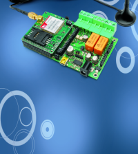
The full GSM thermostat is managed by a Microchip PIC18F46K20-I/PT microcontroller, programmed with a firmware that controls the temperature and takes care of the communication with the GSM module which is the component named GSM; this is, in fact the small board hosting the cell, so the pins’ numbers refer to the used pin-strips’ contacts.
The firmware reads the room temperature by means of a smart probe Dallas DS1820, it controls the logical condition of the opto-isolated input and commands the relay when needed.
Temperature Control Schematic
Having said that, let’s now take a look at the electric scheme, starting by the power block, that from the input voltage (power applied to PWR, + and – must be a continuous current at a value between 5 and 32 V) gets a stabilized component of 3.6 V width by means of a switching regulator. The input voltage is filtered at the bottom by the diode protecting against polarity inversion (D1) through condensers C1 and C2. Fuse F1 enables you to protect both the circuit and the power source in case of short circuit in the integrated regulator discussed below. The regulator is a U1 (a MC34063) and acts as a DC/DC converter step-down; it is used in the classic configuration of the series PWM regulators charged by inductance, whose output voltage depends on the energy stored in L1. The voltage it provides is stabilized providing feedback to the DC/DC through the demotion of a portion of the leveled component by condensers C4 and C5, made by the resistive divider R2/R3.The 3.6 volts present in these condensers are widely filtered by other condensers placed on the power lines of the microcontroller and of the GSM module; which presents, during transmission, absorption peaks compensated for by C7, C8, C13, C14, C15 and C16, thus avoiding than an impulsive current request may cause the microcontroller to be disturbed.
The microcontroller is used in the configuration with an internal clock oscillator; both the scheme and the printed circuit are nevertheless equipped with external quartz, intended for future developments. Once the I/O lines have been initialized, the microcontroller verifies the logical state of the opto-isolated inputs at voltage level related to line RB4 as well as that of lines RC4, RC5, RD0, RD3, RX, which are needed to receive the main notifications from the cellular module; more specifically, RD3 is used to detect incoming calls (it interfaces with the RI of the cellular module), while RC4 controls the GSM “field LED”, by reading the corresponding output status. The PIC understands the conditions of the radio coverage from the frequency and duration of the impulses, and then adjusts accordingly.
The microcontroller contains a UART accessible via pins 44 (transmission) and 1 (reception) which it uses to communicate with the mobile; more precisely, through the first pin (TX), it cyclically questions the module to check whether any SMS has been received, whereas both TX and RX are used for the communication between the microcontroller and the GSM module when making calls and receiving or sending messages.
Regarding the UART, the following control signals are used: CTS (Clear To Send) RTS (Request To Send) and DCD (Data Carrier Detect), which correspond to those of the cellular module being used. Lines RC5 and RD0 complete the set of I/Os destined to the mobile; the former controls the turning on and off of the GSM (through a transistor placed in the small board of the mobile), the latter takes care of resetting the mobile. The button for locally handling the operating mode of the device is read through line RA3, configured as input and equipped with an external pull-up resistor (R11), therefore active at a low level. Special attention deserves the management of the inputs since here, compared to the general scheme of the modular remote, we find a variation: to directly read the condition of the room thermostat contact of the system where the circuit is applied, it must bypass optocoupler U4, for which reason it is not used; let’s imagine to short-circuit pin 1 with pin 4 and pin 2 with pin 3. Input IN1 reading takes place by means of line RB4, set as an input and with an internal pull-up: when the contact is open, it remains at a high level, while when the thermostat closes its contact it assumes the logical zero. IN1 must be connected to the contact normally opened by the eventual thermostat already placed in the system, but only if the enslaved mode (T) is to be activated: in fact, in this mode, relay RL1 follows the performance of the thermostat. IN2 is read by means of RB5, which acquires the U5 optocoupler output transistor status; the input is active when under voltage between 3 and 30 V. When a 3-volt voltage (at a minimum) is applied to input IN2, the optocoupler’s LED is switched on and the output phototransistor is in conduction state; therefore, the collector (pin 5) is at about zero volt during the I/O initialization due to the fall on the resistor of the internal pull-up that was configured. If the input is not polarized, the opto-isolator gets inhibited and its pin 4 is at a high level. Input IN2 can be used to monitor the state of an electric line, for example the one belonging to the alarm indicator of the boiler. Note that IN1 only determines local actions and only in the mode enslaved to the existing thermostat, while IN2 starts the execution of the alarm sequence, which, according to the settings made by the user can be sending SMS or direct calls to the numbers stored in the list. The sequence starts when the input undergoes a potential difference over the threshold one (about 3 volts).
As far as the outputs is concerned, there is just one here, corresponding to RL1. When it has to enable the boiler or the conditioner, the microcontroller puts its own line RE2 at a high logical level, saturating transistor T1 and therefore commanding relay RL1 to be excited; every activation is indicated by LD1, fed along with the relay coil. To protect the collector junction of the transistors during the passage from saturation to interdiction, when the relay’s coil inductance generates inverse voltage peaks, we have connected a diode along with the coil that eliminates such impulses. The complete exchange is available from RL1 so as to manage circuits that require a contact that is normally closed or normally open.
The PIC setting takes place in-circuit, through connector ICSP, related to lines /MCLR, PGU and PGC; the ICSP also receives the power and the mass of the microcontroller.
As this was not enough, we have also prepared a serial communication interface useful to allow the setting of the operating data (for example, the list of phone numbers, the management of input levels, the text of the SMS sent by the circuit in reply to the commands, etc. through a PC: this allows to program a remote control before making it operative and save on the configuration SMS, that can anyway be used, but better if this is done when the system is already installed in its final position. Having already used the UART to communicate with the cellular module, the serial communication takes place through lines RE0 and RA5, respectively used as TX and RX, the AN3, assigned to the A/D inner converter is used to sense the presence of the 5 volts, and therefore the insertion of the connector. The serial interface is at TTL level, and can be easily connected to a USB converter, as for example the FT232 by FTDI, to interface the microcontroller with a PC including a USB. For the interface you can use the small module FT782M made by Futura Elettronica (www.futurashop.it).
Always about the configuration of the unit, note that the corresponding data is not saved in the microcontroller’s EEPROM, but in an external memory chip, named 24FC256-SN; it is a 256 kbit EEPROM CMOS 256 with serial access and I²C-Bus interface. To communicate with it the microcontroller starts lines I/O RD4 and RD5 respectively used as SDA (data line) and SCL (clock line). Moving the configuration data of the remote into an external memory has allowed us to take advantage of the internal EEPROM of the microcontroller to extend the available functions.
The room temperature is sensed by the microcontroller with the help of a vey precise probe, the DS1820 from Dallas Semiconductor, able to measure temperatures in the range 23 °F÷302 °F (-5÷150 °C), with an accuracy of only ± 32.9 °F (0,5 °C) (in the field 14 °F÷185 °F (-10÷85 °C), scan them and make the available on a serial line, connected to the RC0 pin of the microcontroller. The DS18B20 expresses the sensed temperature with an 11-bit resolution; to question it, the microcontroller uses the command “Convert T” (code 44h) corresponding to the launching of the measure conversion. The probe communicates using the one-wire protocol, which allows a two-way communication on a single wire; for that purpose the R19 pull-up resistance is requested. In this application we use separate lines for data and power, but the DS18B20 could also work putting them together, that is using the one-wire protocol to its full potential.


