- How to Adjust X and Y Axis Scale in Arduino Serial Plotter (No Extra Software Needed)Posted 7 months ago
- Elettronici Entusiasti: Inspiring Makers at Maker Faire Rome 2024Posted 7 months ago
- makeITcircular 2024 content launched – Part of Maker Faire Rome 2024Posted 9 months ago
- Application For Maker Faire Rome 2024: Deadline June 20thPosted 11 months ago
- Building a 3D Digital Clock with ArduinoPosted 1 year ago
- Creating a controller for Minecraft with realistic body movements using ArduinoPosted 1 year ago
- Snowflake with ArduinoPosted 1 year ago
- Holographic Christmas TreePosted 1 year ago
- Segstick: Build Your Own Self-Balancing Vehicle in Just 2 Days with ArduinoPosted 1 year ago
- ZSWatch: An Open-Source Smartwatch Project Based on the Zephyr Operating SystemPosted 1 year ago
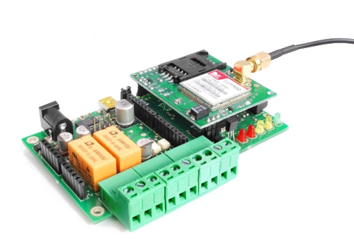
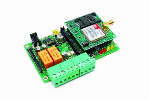
TiDiGino, the Arduino-based GSM remote control
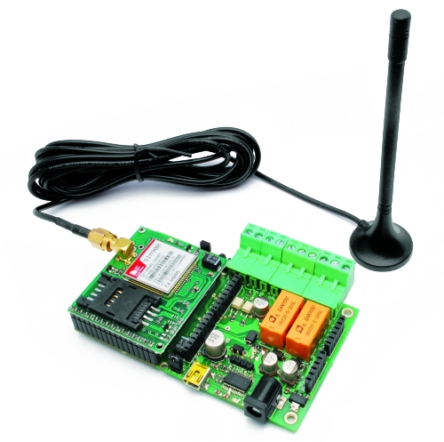
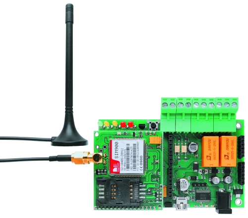
Using an ATmega 2560 and therefore the heart of Arduino, we have developed a universal remote control with GSM. This allows to control 2IN/2OUT, DTMF key, gate control and GSM thermostat activated remotely.
We have already presented several remote control with different functions.
But now we want to present the best remote control ever made with Arduino.
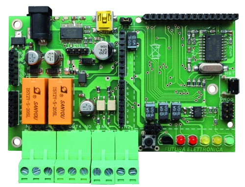
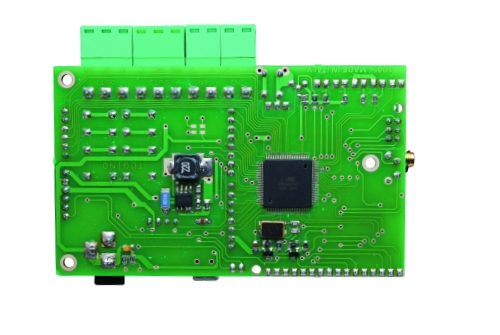
The remote control is easier, thanks to the availability of several libraries that allow you to do anything to the Arduino microprocessor; if there is not really a specific library, you can modify an existing one. Thus was born TiDiGino, based on the chip ATmega 2560 used in Arduino Mega. Our system has connectors S.I.L. to mount any shield, each of them is in the same location where you would be in the original development platform, which enables the use of commercial and in any case the standard shield.
We said that the functions of our remote control, ie 2IN/2OUT, gate opener, key DTMF GSM and thermostat can be achieved by using special firmware, well, we could write these ourselves, but we wanted to offer our readers who know the Arduino environment do them. This is the sense of TiDiGino Contest, which you could follow our blog and that has just ended, as promised, we publish the hardware of the remote control and a few routines.
The circuit
The TiDiGino is based on a ATmega 2560 chip, some pins are used to manage GSM functionality, corresponding to ports that are not used in the original Arduino MEGA. For this reason it is necessary to replace the file pins_arduino.c located under the folder C:\ProgramFiles\arduino-0022\hardware\arduino\cores\arduino that is created by downloading the Arduino IDE, with that we made available with the library, otherwise it is possible to manage all’ATmega 2560 lines of I/O provided by the platform Arduino MEGA.
This choice was intended to leave some I/O free for use by any shield. Therefore you can use the sketches already made to control a specific shield with the original Arduino board, even on TiDiGino.
In compliance with the open-source philosophy we have made available on our site libraries to operate the main blocks of the TiDiGino.
To test the circuit we made four sketches, each of which allows you to use a section of the system. The sketches are all contained in the file GSM_TDGINO.zip, downloadable from the development page of Google, which contains the library that allows you to manage the GSM of TDGINO.
This library comes from the one developed by HWKitchen, but has been adapted to our hardware, as, for example, use the second serial dell’ATMEGA2560 to manage the GSM module of Simcom SIM900. Decompressing the zip in the folder of the Arduino libraries (eg C:\ProgramFiles\arduino-0022\libraries) the library is immediately usable.
By copying the library, are also automatically installed the examples we have developed to manage the various sections, in order to test these examples must be connected to the USB port TDGINO and provide an external power supply circuit of about 12 VDC (1 A of current).
This creates a virtual COM will be used to program the remote control. Select the Board “Arduino Mega 2560” and from File-> Examples-> GSM_TDGINO, choose the example that you want to upload to the remote control.
The hardware
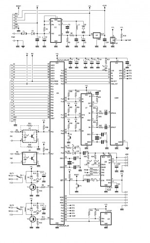
The I/O used for the expansions are PB4÷PB7, PE3÷PE5, PG5, PH3÷PH6, then there are PE0 and PE1 that are, respectively, RXD and TXD of the first internal UART to the microcontroller.
Now we see the lines of I/O used to manage the devices necessary to implement the functions of remote control, starting from PE6 and PE7 configured as input (pull-up R38 and R39) used to read the status of the optically isolated inputs, each of which detects the presence of a dc voltage (from a minimum of 3 to a maximum of about 35 volts) and AC (from a minimum of 2.5 to a maximum of 30 Vrms) applied to IN1 (circuit U4) and IN2 (circuit U5).
The command of the relay output is obtained with PC0 and PC1, initialized as outputs, each relay is controlled by an NPN transistor.
The GSM in the circuit diagram is not the GSM module, but a circuit (TDGGSM_900 – Store) that mounts it.
There is also a EEPROM memory 24FC256-SN to store user data.
For the management of the temperature sensor, used for the feature “Thermostat GSM”, the ATmega use the pin PK1 initialized as two-way line, the remote temperature sensor used in the Dallas DS1820 is capable of measuring temperatures in the range -5 to 150 ° C with an accuracy of ± 0.5 ° C (-10 to 85 ° C).
The DTMF section use the U7 (a MT8870, SMD): capable to decode standards tone thanks to a complex pattern of active filters agreed by the clock signal generated from its oscillator.
The USB interface circuit uses the integrated U8: the classic FT232RL. The pins 3 (TX) and 2 (RX) correspond to the first UART, since they are essentially used to program TiDiGino thanks the bootloader.
P1 is the button to reset the circuit, which also DTR is forced, by the computer when we want to load the firmware in the micro, exploiting the bootloader.
Well, we conclude the analysis with the power, which is a DC voltage, even non-stabilized (applied to the points + and – PWR) in value between 7 and 32 V, this voltage is filtered downstream of the protection diode reverse polarity (D1) by the capacitors C1 and C2, the fuse F1 allows us to protect the circuit and the source of power in an integrated circuit in the controller below and that we need to derive the 4 volts required to make run the rest of the circuit.
BOM
[code]
R1: 0,1 ohm 1W (1206)
R2: 2,2 kohm (0805)
R3: 1 kohm (0805)
R4: 100 kohm (0805)
R5: 4,7 kohm (0805)
R6: 4,7 kohm (0805)
R7: 330 ohm (0805)
R8: 330 ohm (0805)
R9: 4,7 kohm (0805)
R10: 10 kohm (0805)
R11: 4,7 kohm (0805)
R12: 10 kohm (0805)
R13: 330 ohm (0805)
R14: 330 ohm (0805)
R15: 1,5 kohm (0805)
R16: 1,5 kohm (0805)
R17: 330 ohm (0805)
R18: 4,7 kohm (0805)
R19: 4,7 kohm (0805)
R20: 100 ohm (0805)
R21: 4,7 kohm (0805)
R22: 4,7 kohm (0805)
R23: 330 kohm (0805)
R24: 39 kohm (0805)
R25: 56 kohm (0805)
R26: 100 kohm (0805)
R27: 100 kohm (0805)
R28: 4,7 kohm (0805)
R29: 4,7 kohm (0805)
R30: 4,7 kohm (0805)
R31: 0 ohm (0805) *
R32: 0 ohm (0805) *
R33: 4,7 kohm (0805)
R34: 470 ohm (0805)
R35: 470 ohm (0805)
R36: 10 ohm (0805)
R37: 10 ohm (0805)
R38: 4,7 kohm (0805)
R39: 4,7 kohm (0805)
C1: 100 nF (0805)
C2: 220 µF 35 VL (F)
C3: 100 pF (0805)
C4: 100 nF (0805)
C5: 100 µF 16 VL (D)
C6: 100 nF (0805)
C7: 100 nF (0805)
C8: 470 µF 6,3 VL (D)
C9: 22 pF (0805)
C10: 22 pF (0805)
C11: 47 µF 16 VL (D)
C12: 47 µF 16 VL (D)
C13: 100 nF (0805)
C14: 470 µF 6,3 VL (D)
C15: 470 µF 6,3 VL (D)
C16: 470 µF 6,3 VL (D)
C17: 10 pF (0805)
C18: 100 nF (0805)
C19: 10 pF (0805)
C20: 100 nF (0805)
C21: 100 nF (0805)
C22: 4,7 µF 6,3 VL (R)
C23: 100 nF (0805)
C24: 100 nF (0805)
C25: 100 nF (0805)
Q1: Quartz 16 MHz (C7S)
Q2: Quartz 3,579545 MHz (HC49/4H SMX)
U1: MC34063AD
U2: DS18B20+
U3: 24FC256-SN
U4: TLP181
U5: TLP181
U6: ATMEGA2560-16AU
U7: MT88L70AS
U8: FT232RL
U9: TC1262-3.3 (SOT-223)
GSM: TDGGSM_900
D1: GF1M-E3
D2: MBRS140TRPBF
D3: GF1M-E3
D4: GF1M-E3
T1: BC817
T2: BC817
LD1: LED 3 mm red
LD2: LED 3 mm red
LD3: LED 3 mm yellow
LD4: LED 3 mm yellow
LD5: LED 3 mm green
LD6: LED yellow(0805)
LD7: LED red (0805)
L1: coil 22 µH
RL1: relay 5V 2 vias
RL2: relay 5V 2 vias
P1: Microswitch
P2: Microswitch 90°
F1: Fuse 2 A (1206)
– screw 2 vias(2 pz.)
– screw 3 vias (2 pz.)
– Mini-USB
– Plug
– Jumper
– Strip male 2 poli
– Strip male 3 poli (2 pz.)
– Strip male 4 poli
– Strip female 3 poli
– Strip female 6 poli (2 pz.)
– Strip female 8 poli (2 pz.)
– Strip female 16 poli
– PCB
[/code]
Functions
There are several sketches to handle the remote control, all came through TiDiGino contest.
These files can be downloaded from Google, where you will find the library and files created by various readers.
Basically all the sketches perform the same functions.
Summarize here the common features.
The remote can be operated by commands sent by SMS, but you can also control it via the serial port (connected to USB converter).
Each command is followed by a response (via SMS) directly to the sender, but the answer may be disabled. In addition there is an alarm function, as the automatic sending of SMS or voice calls, based on conditions on each of the two inputs.
The circuit can also be used as a gate control, calling the SIM in the TiDiGino: the system recognize the calling number and if this number is stored the relay will switch on. In the DTMF mode, the remote control can be controlled by a multi-frequency telephone tone.
In addition, the circuit can operate as a thermostat, running an air conditioning system.
In summary, there are the following features:
• Remote alarm
• Gate control
• GSM termostat
• Remote control with DTMF
Library and sketch
Download the latest sketch for this GSM remote control.
Design
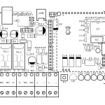 |
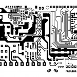 |
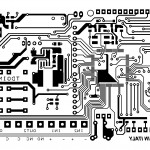 |



Pingback: TiDiGino, the Arduino-based GSM remote control | The World of Open | Scoop.it
Pingback: GSM remote control with the TiDiGino | My Blog
Pingback: TiDiGino, the Arduino-based GSM remote control | Open Electronics | Arduino Focus | Scoop.it
Pingback: GSM remote control with the TiDiGino « Uncategorized « Cool Internet Projects
Pingback: TiDiGino Contest | Open Electronics
Pingback: Electronics-Lab.com Blog » Blog Archive » TiDiGino – Arduino-based GSM remote control
Pingback: styczen
Pingback: styczen
Pingback: styczen
Pingback: countydrugcard.org
Pingback: Arduino Full Memory: upgrade Arduino IDE | Open Electronics