- How to Adjust X and Y Axis Scale in Arduino Serial Plotter (No Extra Software Needed)Posted 7 months ago
- Elettronici Entusiasti: Inspiring Makers at Maker Faire Rome 2024Posted 7 months ago
- makeITcircular 2024 content launched – Part of Maker Faire Rome 2024Posted 9 months ago
- Application For Maker Faire Rome 2024: Deadline June 20thPosted 11 months ago
- Building a 3D Digital Clock with ArduinoPosted 1 year ago
- Creating a controller for Minecraft with realistic body movements using ArduinoPosted 1 year ago
- Snowflake with ArduinoPosted 1 year ago
- Holographic Christmas TreePosted 1 year ago
- Segstick: Build Your Own Self-Balancing Vehicle in Just 2 Days with ArduinoPosted 1 year ago
- ZSWatch: An Open-Source Smartwatch Project Based on the Zephyr Operating SystemPosted 1 year ago
Octopus, a “tentacular” shield for Arduino and Fishino
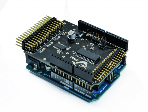
A shield that provides 16 digital or PWM I/O using a single Arduino/Fishino I²C bus. Ideal for managing multi-color LED or servo motors.
Arduino boards and compatible alternatives are really easy use and o powerful, capable of making countless applications, but they suffer from two strong limitations: the relatively small program memory and the limited number of available outputs, especially when coming to PWM signals. For example, the Arduino / Fishino ONE has only six PWM outputs and, unless you generate the related signals via software (with considerable processor load), you can control one driver only, i.e. a single RGBW power LED or alternatively six monochromatic LEDs.
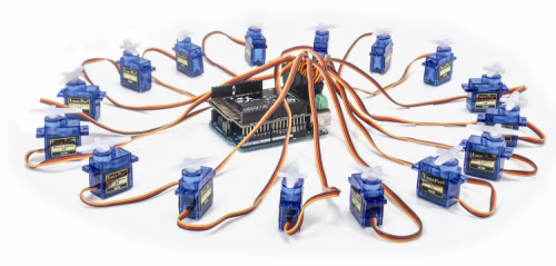
This limitation becomes painfully evident when you want to drive more than 6 servo-motors with a single board: moving a “hexapod robot type”, which requires 12 servomotors, is impossible.
Digital inputs and outputs are limited too; always talking about Arduino boards, we have a total of 13 digital I / O and 6 analog inputs (those can also be used as digital).
The total number can be judged as sufficient for many uses, but you have to consider that many of these are used by onboard devices or by expansion shields.
In practice, if you make a project with an Ethernet/WiFi shield, a SD memory, a serial port and some analog inputs, you have only six digital I / O left, that are often insufficient to medium complexity projects.
For all these reasons we have decided to design an expansion shield, compatible with all Arduino boards and with our Fishino UNO (and Fishino Mega that we’ll launch soon) that almost without consuming hardware resources provides 16 PWM outputs and 16 additional digital inputs/outputs. In addition, you can connect up to 8 shields, giving Arduino up to 128 PWM and I/Os, that can be managed in a total transparent way by the user through a specific library.
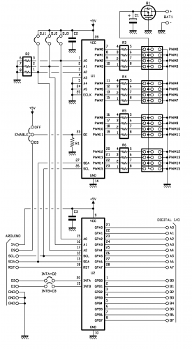
Wiring diagram
The shield we made consists of three blocks:
- digital I / O block;
- PWM block;
- external power supply reverse polarity protection circuit
Digital I / O block
This section is based on the well-known integrated MCP23017, the I²C bus interface version: it is connected with two wires only, clock (SCL) and data (SDA).
There is also a SPI interface version, faster but needs four CPU lines, therefore we didn’t choose it.
Like all the I²C devices, the chip is activated only if its own address matches with the “destination” address sent as a bit sequence over the two wires.
For MCP23017, its address is composed by a fixed part (referred as MCP23017_I2C_BASE_ADDRESS in our library) equal to 0x20 hex whose last three bits are configurable by three external pins (A0, A1 and A2) so the final address can vary from binary 000 (0 decimal) to 111 (decimal 7), from 0x20 to 0x27 hex. We need 8 different addresses to connect to the same I²C bus eight MCP23017 (i.e. 8 different shields, each with its unique address).
The integrated has two 8-bits digital I/O (GPA0 ÷ GPA7 and GPB0 ÷ GPB7), 16 total lines, individually configurable as input or output, with or without internal pullup resistors, through the software library we’ll analyze in a moment.
For each 8-bit channel the chip is able to generate an interrupt signal on the INTA and INTB outputs, for any inputs change of state, either separately for each 8 ports group (the hardware can distinguish between the two channels) or one single interrupt signal for all inputs.
Interrupts generated when an input changes, is a great advantage when you need to get immediate answers to external events and compensate for the limitation we have on Arduino / Fishino UNO that handle only two interrupt inputs.
The INTA and INTB outputs can be connected by two jumpers to Arduino addresses 2 and 3, the only ones able to detect a change of state; through software you can then choose whether to use both, only one or none.
The decoupling capacitor C3, located near the chip, avoids that power line noise could affect the microcontroller lines while the RST line, connected to Arduino reset pin, restores the board at boot or by pressing the RESET button.
PWM section
This section is based on the less known but really versatile PCA9685, an integrated able to generate 16 PWM almost-independent signals (we shall see in the libraries description that the frequency must be the same for all outputs).
This integrated supports a six bits addressing, via the A0…A5 inputs, which means up to 64 different boards managed; However, being the limit imposed by the 8 cards Micro (and since 64 boards connected to a single bus are way too many) we used only A0 ÷ A2 bits, keeping the possibility to connect eight different devices and connecting the remaining pins (A3…A5) directly to ground. The PWM frequency is set through an internal register (pre-scaler) with the following formula:
This chip can generate the clock frequency both internally by means of a 25 MHz oscillator (which allows to obtain PWM frequencies from 24 to 1,526 Hz) and by an external clock up to 50 MHz
Unlike the MCP23017, this integrated does not have a reset pin; that function should be software implemented (there is a special I²C address for the reset) or simply by restoring the registry via software (which we do through the library). Instead, we have an OE input to disable all outputs simultaneously: we connect it by a jumper to Arduino D9 pin, in case you need to force the shield reset.
An interesting possibility available on this integrated is that it can configure its outputs both in totem-pole mode, with a pair of complementary MOSFETs, able to provide both a positive (source) and negative (sink) current with respectively 10 mA or 25 mA (at 5 volts) maximum values, and in open-drain mode (or open collector in Italian) that can provide only a negative current up to 25 mA (this mode is useful in some cases).
Those features (and others that we omit here for brevity) show that the integrated was born to PWM drive LEDs, connected directly to its outputs via resistors; it can be used for numerous other applications as well.
On the wiring diagram you can see, in fact, resistors in series to the outputs (protecting from overcurrent) that lead to a three-pin output connector. Besides the PWM pin, we have the ground and a positive voltage we’ll investigate later. This connector, 90 ° angled, allows to connect 16 servo motors directly without interfering with other Octopus additional shields.
Reverse polarity protection
As we mentioned before, the card is designed to drive servos directly, connecting them to the angled connector. These components absorb a remarkable peak current and it is unthinkable to use the 5V Arduino power supply; It was therefore provided a connector for an external voltage. To prevent reverse polarity damages to both the board and the servo controllers, we put in series to the power input the P-channel Q1 MOSFET that permits the current flowing only to the correct direction.
Why a MOSFET and not a simple diode? The reason is that the diode has a fixed voltage drop at its terminals (slightly variable with the current) that, being safe for the medium-high voltages and low currents, will cause considerable losses and overheating in case of high currents and low voltages.
For example, choosing a Schottky diode with a voltage drop of around 0.5 V, a 4 amperes current dissipates 2W: and a 2-watt diode is big and gets really hot.
Instead, the MOSFET has a particularly low conduction resistance, equal to 51 mOhm (milliohms) at the same drain current. The dissipation becomes therefore equal to:
A much lower power to be dissipated, resulting in less overheating and greater duration of any batteries. The electrolytic capacitor C1 filters the input voltage from unexpected noise. The value chosen, 100 uF, is enough up to a few amps current; in case of higher currents and / or very impulsive absorptions we suggest to insert an additional high capacity external capacitor on the power line.
Practical implementation
The shield is made by a double-sided printed circuit with plated holes and uses SMD components; being a surface mounting, you need the usual attention, especially for the smallest components and those with closely spaced pins.
The highest attention is required by the PCA9685, supplied in 28-pin TSSOP28 package with pin spacing of only 0.65 mm, and by the resistive R3 ÷ R6 networks, which have small and very close pins; pay attention also to the electrolytic capacitor C1 which, even if it’s not small, has very short. With a little practice, a magnifying glass and tweezers, a good fine-tipped soldering iron (not more than 20 W) and excellent flux paste (which helps to melt and distribute the soldering wire on pins and pitches) is still quite simple to make the circuit; if we drop too much solder alloy and make a short circuit between pins you can remedy by sprinkling flux paste, cleaning up very well the soldering iron tip and heating them. Usually with 2-3 passages, even the most difficult short circuits are resolved in this way.
We need only to pay attention to the chip temperature, avoiding to keep the welder in the same position too long and, if it is necessary to repeat the process, cool for few seconds the component.
If you prefer not to assembly your own PCB, you can purchase it on our website www.futurashop.it but the side and front connectors are not mounted since we what to offer the chance to change the connector types.
The software library
As already mentioned, for this board we have specifically developed a software library, called Octopus, equipped with some special features that make it easy to use.
The first interesting feature of the library is in the include file (Octopus.h):
#define Octopus __octopus ()
OctopusClass & octopus __ ();
and from the source file lines (Octopus.cpp):
OctopusClass & octopus __ ()
{
 static OctopusClass octo;
 return octo;
}
This weird use of the Octopus variable fixes on of the C++ main problems, i.e. the initialization of global variables does not happen in a predetermined order, but is random when the sketch is loaded. In our case, having to initialize the I²C interface by using the instructions:
Wire.begin ();
Wire.setClock (400000);
before the use of the library, it is impossible to create the static variable Octopus when loading the program, given that the Wire interface has not been initialized yet. The chosen solution allows to create the variable in the very moment it is needed, so after initializing properly the I²C-bus interface;
This has allowed us to create a code, with no additional program line, to count and init correctly all the connected Octopus shields and automatically assign a number to their outputs based on their I²C address. For example, if we apply this to our Arduino 2 Octopus shields, we will have 32 digital I/O, numbered from 0 to 31, and 32 PWM, also numbered from 0 to 31.
The library provides two functions that allow you to know the number of connected boards and the number of I/O and PWM available:
// Return number of boards found
uint8_t getNumBoards (void) const;

// Return number of available I / O
uint8_t getNumIO (void) const;
As mentioned earlier, the PWM frequency is unique for each board, i.e. for each group of 16 PWM outputs; it can be set using the following two functions, the first board to board and the second for all the connected cards in one command:
// set PWM frequency for a single connected board
// Valid values 24 Hz ... 1526 Hz
void setPWMFreq (uint8_t board, uint16_t freq);

// set PWM frequency for ALL connected boards
void setPWMFreq (uint16_t freq);
In the first you should pass the board number (ranging from 0 to Octopus.getNumBoards ()) and the PWM frequency, from 24 Hz to 1,526 Hz; for the second command, just indicate the frequency set to all boards. At power up, the default frequency is 200 Hz, suitable for servo control and LEDs. The PWM output value can be set, similarly to Arduino, by using the following function:
 // PWM output
void analogWrite (uint8_t port, uint16_t val, bool invert = false);
For example, to set the output 30 to 50% of the maximum value, you must type:
Octopus.analogWrite (30, 2048);
The third optional parameter, invert, is useful if you connect LEDs to the open collector outputs with their anodes to the positive voltage: in this case you need a reverse output, the more it is high the less current flows, so you have to specify this behavior the manage correctly the brightness set by the variable val.
As you may have noticed the PWM value, unlike Arduino outputs, is 16 bits while only 12 are used, thus allowing a 4096 intensity level granularity (instead of 256 on the standard Arduino PWM). This allows, for example, a much more gradual LED light intensity control. On the other hand, it is necessary to remember this when you set the value, considering that a number of 255, which corresponds to the maximum intensity of Arduino, here corresponds to a rather low value (255 / 4,096 of the maximum).
For the digital I / O management, the library provides the following functions, practically identical to those from the standard libraries:
// Digital I / O
void pinMode (uint8_t port, uint8_t mode);
bool digitalRead (uint8_t port);
void digitalWrite (uint8_t port, bool value);

// Read / write all digital pins of given board at once
uint16_t digitalReadAll (uint8_t board);
void digitalWriteAll (uint8_t board, uint16_t val);
The last two functions allow you to read and write all digital ports for a card in one pass, using a 16-bit variable; This is very handy in case you need to write or read quickly the digital ports.
The library described so far is under continuous development, so check all the latest features on the project website fishino.
A test sketch
Finally, we present a simple sketch that displays a “tail” light by using 16 LEDs connected to the PWM outputs (Listing 1).
Listing1
// Project : OctopusTest
#include <Wire.h>
#include <Octopus.h>
uint16_t i = 1;
uint16_t valueTable[16];
// initialization code
void setup(void)
{
Serial.begin(115200);
Serial.println("OCTOPUS TEST APP");
Wire.begin();
Wire.setClock(400000);
delay(500);
Serial.print("Found #");
Serial.print((int)Octopus.getNumBoards());
Serial.println(" OCTOPUS boards");
delay(500);
Octopus.setPWMFreq(1526);
for(int k = 0; k < 16; k++)
valueTable[k] = (- (double)k * k / 64 + 0.25 * k) * 4096;
}
// endless loop
void loop(void)
{
for(uint8_t p = 0; p < 16; p++)
Octopus.analogWrite(p, valueTable[(i + p) % 16]); i++;
delay(50);
}
The code initializes the serial interface, prints a message, initializes the I²C, prints the number of detected boards and, using the first of them (PWM outputs from 0 to 15) creates a kind of bright ‘snake’ using 16 LEDs.
The brightness values of the ‘snake’ are previously calculated in the setup and entered in a table containing 16 values; depending on the table starting cell (variable ‘i’ in the loop) the ‘head of the snake’ is put in a different place, thus creating the visual effect desired.
As you can see, the library can be used as the normal Arduino control library with the only variation to put ‘Octopus.’ before analogWrite () commands.
The interesting thing can be the second order polynomial function that reckons the brightness values to be put in the tab, to create a wave effect. You can use other functions like linear variation or trigonometric functions as well.
for (int k = 0; k <16; k ++)
 sinTable [k] = 4096 * sin (M_PI / 16 * k);
For a sinusoidal shape, or
 for (int k = 0; k <16; k ++)
 if (k <= 8)
 sinTable [k] = 4096 * (double) k / 8;
 else
 sinTable [k] = 4096 * (double) (15 - k) / 8;
for a bilinear trend.
We conclude here the description of our Octopus board; you can now experience the different lighting effects by using e.g. the Colibrì (Hummingbird) drivers presented in the last issue of openelectronics blog.


Pingback: The Pianist Octopus: a gadget to blow minds | Open Electronics