- How to Adjust X and Y Axis Scale in Arduino Serial Plotter (No Extra Software Needed)Posted 7 months ago
- Elettronici Entusiasti: Inspiring Makers at Maker Faire Rome 2024Posted 7 months ago
- makeITcircular 2024 content launched – Part of Maker Faire Rome 2024Posted 9 months ago
- Application For Maker Faire Rome 2024: Deadline June 20thPosted 11 months ago
- Building a 3D Digital Clock with ArduinoPosted 1 year ago
- Creating a controller for Minecraft with realistic body movements using ArduinoPosted 1 year ago
- Snowflake with ArduinoPosted 1 year ago
- Holographic Christmas TreePosted 1 year ago
- Segstick: Build Your Own Self-Balancing Vehicle in Just 2 Days with ArduinoPosted 1 year ago
- ZSWatch: An Open-Source Smartwatch Project Based on the Zephyr Operating SystemPosted 1 year ago
GSM/GPRS & GPS modem with SIM900/SIM908 module
Allows you to create data connections on the GSM network through a standard USB interface.
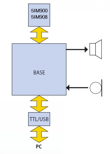
The cellular modems, particularly USB-stick ones, are now at very affordable prices, however they’re limited: they are explicitly designed for Internet connections, so you cannot use it as a normal modem and so implement, for example, a point to point data communications with them. The GSM modems that allow this are quite rare, and so we create and offer you one: it is a device for PC with an USB interface with “voice” functions: there is a jack for a speaker and one for microphone.
The circuit is made simple by the adoption of a mobile phone module of Simcom SIM908 and SIM900 of the SIMCom. The USB connection is implemented with the aid of a converter TTL / USB type FT782M. Our modem is ideal to perform data links without access to the GPRS network or in any case to the Internet and allows, for example, the use in point-to-point mode, locators GPS / GSM or GSM only so as to obtain instantly data positioning and follow moves on live. In short, it allows direct data connection with another modem or mobile phone provided of a modem, but without going through the web: connections are made directly to the GSM data channel.
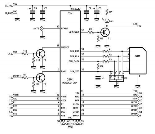
Wiring diagram
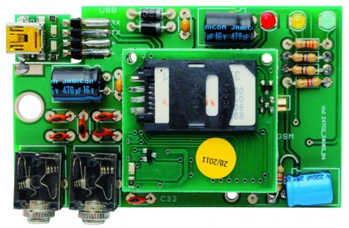
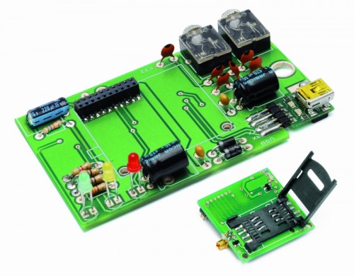
The circuit consists in a Simcom module and a few discrete active and passive electronic components; the conversion interface from TTL to USB is a small module that applies to USB contacts and connects to RX and TX cell module.
The connector carries power supply (Vcc, contacts 17 and 19 – GND, contacts 18 and 20) in addition to the power-on signal (PWR), and all signals and serial communication lines to and from the GSM module.
The ON/OFF line is connected to a R/C circuit that, at power of the entire circuit, considering that C11 is discharged puts it to hte logical zero; this condition leaves the transistor T2 of the mobile phone module interdict and maintains logical 1 to the PWR Contact of the SIM900/SIM908. When the capacitor is charged enough to saturate the T2 transistor, these places at the bottom level the PWR line of the GSM and turn on the mobile phone.
There are two contacts for the microphone (differential input) and two contacts for the speaker: pins 19, 20, 21, 22, which correspond respectively to MIC1P and MIC1N (positive and negative) and SPK1N and SPK1P (respectively negative and positive of the speaker).
The antenna of the GSM module is connected directly on the PCB of the cell on a special type of miniature coaxial MMCX connector.
The main power is provided by the 5 volts coming from USB, the absorption of the mobile phone module does not exceed the granted limit (500 mA) from this type of connection.
C1 and C2 filter the voltage and D1 and D2 subtract about 1.4 volts, because SIM900/SIM908 work with a maximum of 4 volts, filtered by C3 and C4 to reduce noise (note the resistor R1, which discharges such capacitor when the circuit is private of supply).
Light emitting diodes LD1 and LD2 are used to monitor data traffic, respectively, received on the RX line and sent from the TX.
Bill of materials
[code]
R1: 330 ohm
R2: 47 ohm
R3: 47 ohm
R4: 4,7 kohm
R7: 56 kohm
C1: 100 nF
C2: 470 µF 16 VL
C3: 100 nF
C4: 470 µF 16 VL
C5: 47 pF
C6: 47 pF
C7: 47 pF
C8: 47 pF
C9: 47 pF
C10: 47 pF
C11: 220 µF 16 VL
D1: 1N5819
D2: 1N4007
LD1: LED 3 mm red
LD2: LED 3 mm yellow
LD3: LED 3 mm green
USB: TTL/USB (FT782M)
female strip 2×10 via 2 mm
Jack 3,5mm (2 pz.)
[/code]
Use of the modem
To use our modem first must install a virtual serial port loading on the computer FT232RL drivers, downloadable for free from www.ftdichip.com .Once the drivers are installed, connect the modem, with USB/mini-USB cable, and wait while it is found and the drivers are actually installed.
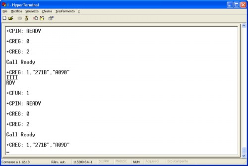
After that, you can already use the product by opening a terminal window (Windows Hyper Terminal is fine …) you can handle the modem by issuing the AT commands for the SIM900/SIM908.
The communication session from a terminal must be opened on the virtual COM assigned by the operating system with the following parameters: speed 115.200 bps, 8 data bits, 1 stop bit, no parity, hardware flow control disabled.
After starting the communication session with Hyper Terminal, the screen shows all the time diagnostic information and other data coming from the SIM900/SIM908 modem; into the screen you can give appropriate commands, perhaps starting with a reset (ATZ). You can also do a simple test first, giving the command ATD NNNNNNNNN where NNNNNNNNN is the number to dial, putting the number of mobile phone with a modem and pressing Enter, you will see soon the phone’s display the incoming data message.If you give the command ATD NNNNNNNNN followed by ; the call will be on a normal mode (vocals) and the called phone display will show only the incoming call alert.









Pingback: GSM modem means wireless serial connections | ro-Stire
Pingback: GSM modem means wireless serial connections » Geko Geek
Pingback: GSM/GPRS & GPS modem with SIM900/SIM908 module | Make, Electronics projects, electronic Circuits, DIY projects, Microcontroller Projects - makeelectronic.com
Pingback: GSM modem means wireless serial connections ¶ jmcgready's miscellany
Pingback: Gps Gsm Module | Garmin Approach
Pingback: Small Gps Module | Garmin Approach
Pingback: Gsm Gps Module | Garmin Approach
Pingback: 2regulatory