- How to Adjust X and Y Axis Scale in Arduino Serial Plotter (No Extra Software Needed)Posted 7 months ago
- Elettronici Entusiasti: Inspiring Makers at Maker Faire Rome 2024Posted 7 months ago
- makeITcircular 2024 content launched – Part of Maker Faire Rome 2024Posted 9 months ago
- Application For Maker Faire Rome 2024: Deadline June 20thPosted 11 months ago
- Building a 3D Digital Clock with ArduinoPosted 1 year ago
- Creating a controller for Minecraft with realistic body movements using ArduinoPosted 1 year ago
- Snowflake with ArduinoPosted 1 year ago
- Holographic Christmas TreePosted 1 year ago
- Segstick: Build Your Own Self-Balancing Vehicle in Just 2 Days with ArduinoPosted 1 year ago
- ZSWatch: An Open-Source Smartwatch Project Based on the Zephyr Operating SystemPosted 1 year ago
An LCD Expansion Shield for your RaspberryPi
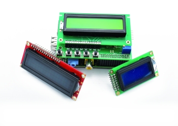
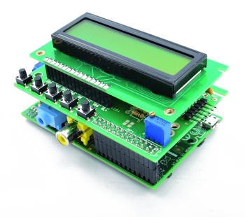
Today we introduce a great LCD expansion shield for Raspberry Pi that allows you to create an interface to control applications without the need to constantly keep a monitor, keyboard and mouse connected.
Cool! Isn’t it?
The enhanced value of a micro PC as Raspberry Pi with respect to a classic microcontroller is to be able to perform various tasks in resource sharing. Beyond the devices already available on the board you can add more, just being limited by the number of I/Os, processing power and memory.
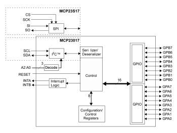
In this post we describe the hardware of the shield, a library that terrifically improves the shield ease of use and a little deepening about the MCP23017, which has been used as an interface between the Raspberry Pi and the LCD modules.
Much of the potential and use cases depend on how the apps are designed, especially with regard to the ability to share resources used and avoid unsolvable deadlocks. Take for example the shield described in this article, which, as we shall see, requires the use of the I2C bus for the communication with Raspberry Pi.
In fact, in case we wanted to build an application using the LCD exclusively the software is equivalent to what we would have written for a microcontroller. A program that runs in an infinite loop, managing the buttons and showing information on the screen.
If we want that the LCD display to serve a multiplicity of applications we should handle things differently. Let’s say we want to use the shield as in the previous case, but also allowing different applications to display messages, for example, for notifications such as phone calls or whatever.
In such an architecture, the different applications work simultaneously and in correspondence with given events, they require access to the I2C bus and then to the LCD to communicate their message.
If an application is already using the bus, other applications requiring to bind the same bus, finding it busy can’t do anything but go error. The first solution that might come to our mind is to create a single application handling all the needs in a monolithic way, a bit like a huge microcontroller.
This would lead to more negative than positive aspects such as application rigidity, difficulty in planning, maintenance and updating, difficulties in managing inter-parts timing, fragility (if something insignificant blocks, all the applications crash).
To solve such a need you should better rely on an architecture based on servers that can support concurrent applications, orchestrating the access to shared resource and where the different client application requirements can be fulfilled. For example, assume that two parts exclusively use the resources assigned to them: the LCD shield with the I2C bus and the GSM / GPS shield (which we already presented here), which uses the serial port.
For each of these resources is necessary to create a “server” or “demon” that manages the resource autonomously and manages the different clients requests on a predefined channel. There are many possible alternatives: TCP / IP sockets, semaphore files, and so on: in fact it’s all about managing “traffic lights” to properly coordinate client requests and forcing clients, ultimately, to access a centrally managed resource using the default communication channel with the protocol and the procedures previously defined. Better or worse than the microcontroller? This question does not have a definitive answer: it depends on what you want to accomplish and the requirements associated with it. Surely we will find ourselves increasingly in a position to integrate and these two environments with others such as FPGA and PLC.
Having said that, let’s get back to our shield.
The diagram
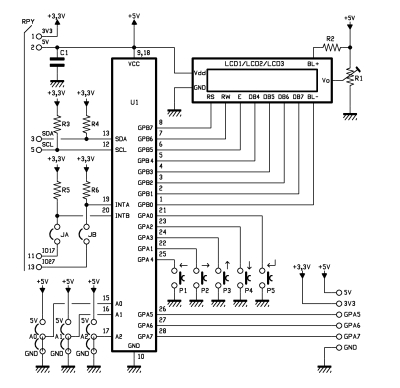
To avoid to bind most of the input/output pins available on the Raspberry Pi connector just for the LCD functionality, we used the Microchip MCP23017 component which offers 16 Digital I/Os controllable through the I2C bus. In this way, we take advantage (also in a non-exclusive manner) of only two pins to drive the LCD screen, to interface five switches and manage three auxiliary inputs.
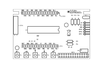
The basic configuration is designed to create a cascading menus system that allows to choose between hierarchies of items and then to configure parameters and visualize data. In reality, programmatically, we could use the buttons and inputs as we wish. The shield is provided with several connectors that can accommodate different types of LCDs which, while having different size, share the same pin configuration and commands.
The MCP23017 provides 16 digital I/Os divided into two banks of eight lines each, named GPA and GPB. The GPB is entirely dedicated to the LCD display management, while the five button are connected to the pins of the GPA.
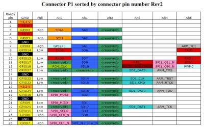
A 5V power is taken from pin 2 of the GPIO connector on the board and the ground is connected to pin 6. The 10 kOhm potentiometer, connected to V0 pin of the LCD allows you to adjust the intensity of the backlight.
INTA and INTB outputs are connected, by means of the JA and JB jumpers, to GPIO17 and GPIO27, in order to make them available to possible applications. On the shield you can also find a a comb connector exposing also GPA5, GPA6 and GPA7 pins of the MCP23017, left over from the buttons management needs.
The practical use of the shield
First step: let’s assemble one of the LCD displays on the shield and then mount the shield on the Raspberry Pi’s connector.
Let’s than connect the peripherals, network, and power the Raspberry Pi in the usual way.
To communicate with the MCP23017 we must to use the I2C bus: as a result we have to power the I2C management module that, in a default Raspbian installation, is disabled. We must first enable the driver to manage the I2C bus, then install the python library for the LCD management and then make a first test program to see that everything is working properly.
First go with the following commands (as user “root”):
apt-get update
apt-get upgrade
subsequently to use the I2C bus management module you must remove it from the blacklist and then add it to the set of modules available to the kernel .
Open the configuration file that contains the list of blacklisted modules, with the command:
nano /etc/modprobe.d/raspi-blacklist.conf (nano is a minimalist text editor that runs inside the terminal).
And eliminate the I2C module from the blacklist by erasing the lines or just commenting it with a “#”
You have to save the file and reboot for the changes to take effect.
Now we need to make sure that the two modules are loaded in the kernel. We can do this in two ways: loading the modules dynamically by command line (making them available for the entire session, at the next boot the modules need to be reloaded) or by loading the modules directly during the boot phase, which is essential in a system that runs unattended, especially thinking of resets.
The first option requires the use of the command modprobe (command: modprobe i2c-dev). Modprobe can be also used to disable a previously loaded module by using the remove option in the command (modprobe-r i2c-dev).
If you want the modules to be loaded in the kernel at the boot phase, after having whitelisted them as we saw above, you’ll need to enable permanent loading by modifying the configuration file /etc/modules, which contains the list of drivers to load at boot time. To edit the file we can use the command:
nano /etc/modules
and add a new line to the configuration file that contains
i2c-dev
In any case, you can always check the success of the activation of the driver by displaying the list of all installed modules with the lsmod command. Also, as in Linux everything (or almost) is a file if you go in the /dev folder you’ll see link files to devices i2c-0 and i2c-1.
Now let’s install the i2c-tools package, that provides a number of functions you can use with command line to verify the operation of the i2c bus:
apt-get install i2c-tools
and then add our user to the i2c group:
adduser pi i2c
Then reboot the RaspberryPi to activate the new configuration with the reboot command.
After RaspberryPi reboot connect with with Putty or Kitty to check whether the I2C bus is visible to the ADC with the command
i2cdetect -y 0 per RaspberryPi rev. 1 or
i2cdetect -y 1 per RaspberryPi rev. 2
You will get a result that is similar to that shown in the figure where the address 0x20 identifies the MCP23017.
Now we can install the LCD support library. We will use the library made available under the BSD license by Adafruit Industries in the GitHub repository.
The best procedure to download it is to use the version management tool invented by Linus Thorvalds, called git.
To install “git” we use the command:
apt-get install git
then we go to the home directory with the command:
cd /home
and create a folder for our project, (for example LCD) by means of:
mkdir LCD
Then move in the folder with the command:
cd LCD
and download the python libraries made from Adafruit with:
git clone https://github.com/adafruit/Adafruit-Raspberry-Pi-Python-Code.git
finally move in the folder that contains the library for the LCD management with the commands:
cd Adafruit-Raspberry-Pi-Python-Code
We can see the contents of the folder by positioning ourselves there with WinSCP.
Let’s move in the folder that contains the Adafruit_CharLCDPlate library with the command:
cd Adafruit_CharLCDPlate
Then let’s install the I2C protocol management library for python:
apt-get install python-smbus
At this point, we’re almost ready to test the operation of the LCD shield.
In the Adafruit_CharLCDPlate library, GPA6 and GPA7 pins are used for color management in a RGB color LCD. In our case, as we use a monochrome LCD, these pins are free. To use them for other purposes you must obviously modify the library.
The library contains the code for the Adafruit_CharLCDPlate class. In the constructor of the class we modified the initial registers settings to make the GPA5, GPA6 and GPA7 as input pins with internal pull-up resistor and operated on inverted logic (value “1” when the pin is grounded).
In particular, we modified the following lines:
line 99 [ 0b11111111, # IODIRA R+G LEDs=outputs, buttons=inputs orig. 0b00111111
line 101 0b11111111, # IPOLA Invert polarity on button inputs orig. 0b00111111
line 112 0b11111111, # GPPUA Enable pull-ups on buttons orig. 0b00111111
In line 425 we modified the backlight method to eliminate the use of pins on the GPA pool for the color management.
def backlight(self, color):
c = ~color
# self.porta = (self.porta & 0b00111111) | ((c & 0b011) << 6)
self.portb = (self.portb & 0b11111110) | ((c & 0b100) >> 2)
# Has to be done as two writes because sequential operation is off.
# self.i2c.bus.write_byte_data(
# self.i2c.address, self.MCP23017_GPIOA, self.porta)
self.i2c.bus.write_byte_data(
self.i2c.address, self.MCP23017_GPIOB, self.portb)
Finally (in line 436) we added three methods for reading the individual “advanced” pins.
# Read and return bitmask of pin A5
def buttonpin5(self):
return (self.i2c.readU8(self.MCP23017_GPIOA) >> 5) & 1
# Read and return bitmask of pin A6
def buttonpin6(self):
return (self.i2c.readU8(self.MCP23017_GPIOA) >> 6) & 1
# Read and return bitmask of pin A7
def buttonpin7(self):
return (self.i2c.readU8(self.MCP23017_GPIOA) >> 7) & 1
We have prepared a test program by changing the one included in the library folder visible finally getting the program visible in Listing 1. The program allows, by pressing the buttons on the shield, to obtain information on the system’s current status and performances, summarized them in the LCD.
Copy the program in a file named LCDProva.py.
Remember to run the command:
modprobe i2c-dev
Move in the Adafruit_CharLCDPlate folder and run the program with the command:
python LCDProva.py
You should see the opening message on the LCD and then the buttons menu.
If you can’t see nothing or you have too much contrast you can adjust that by tuning the R1 potentiometer until you get a satisfactory result.
As you can see the list is very simple: most of the work is done by the methods provided by the library. When the program starts you can see that we import the sleep class (to manage the execution delays), the Adafruit_CharLCDPlate and the subprocess library.
The first instruction of the program invokes a method that allows you to determine which is the revision of the Raspberry Pi board we’re using and accordingly set the I2C bus, 0 or 1. Then the program sends the display opening message, and then (one second later) the menu prompt.
Finally, the while loop helps reading the values of the three input pins, button presses are intercepted, corresponding actions are performed and the results are presented on the display. The pin values are presented in the lower right of each command display.
For a purely didactic purpose, in this sample program, we wanted to present the result of some commands that allow you to collect information on your system’s status and performance. Needless to say, the same commands can be typed in the terminal window as normal controls, obtaining the same results.
Commands were executed by launching processes that are external to the program and retrieving the result at the end of processing.
Listing 1
#!/usr/bin/python

from time import sleep

from Adafruit_CharLCDPlate import Adafruit_CharLCDPlate

from subprocess import *

cmd_ip = "ip addr show eth0 | grep inet | awk '{print $2}' | cut -d/ -f1"

cmd_cpu = "mpstat | awk '$11 ~ /[0-9.]+/ { print 100 - $11}'"

cmd_dfh = "df -h | grep /dev/root | awk '{ print $2 }'"

cmd_dfh_p = "df -h | grep /dev/root | awk '{ print $5 }'"

cmd_ps = "ps -ef | wc -l"

def run_cmd(cmd):

       p = Popen(cmd, shell=True, stdout=PIPE)

       output = p.communicate()[0]

       return output

class CPU(object):

  def __init__(self):

     """Init a CPU status object"""

     stat_fd = open('/proc/stat')

     stat_buf = stat_fd.readlines()[0].split()

     self.prev_total = float(stat_buf[1]) + float(stat_buf[2]) + float(stat_buf[3]) + float(stat_buf[4]) + float(stat_buf[5]) + float(stat_buf[6]) + float(stat_buf[7])

     self.prev_idle = float(stat_buf[4])

     stat_fd.close()

  def usage(self):

     """return the actual usage of cpu (in %)"""

     stat_fd = open('/proc/stat')

     stat_buf = stat_fd.readlines()[0].split()

     total = float(stat_buf[1]) + float(stat_buf[2]) + float(stat_buf[3]) + float(stat_buf[4]) + float(stat_buf[5]) + float(stat_buf[6]) + float(stat_buf[7])

     idle = float(stat_buf[4])

     stat_fd.close()

     diff_idle = idle - self.prev_idle

     diff_total = total - self.prev_total

     usage = 1000.0 * (diff_total - diff_idle) / diff_total

     usage = usage / 10

     usage = round(usage, 1)

     self.prev_total = total

     self.prev_idle = idle

     return usage

  def memUsage():

     free_fd = os.popen('free -b')

     free_buf = free_fd.readlines()[1].split()

     usage = (float(free_buf[2]) / (float(free_buf[1]))) * 100

     usage = round(usage, 1)

     return usage

cpu = CPU()

# Initialize the LCD plate.  Should auto-detect correct I2C bus.  If not,

# pass '0' for early 256 MB Model B boards or '1' for all later versions

lcd = Adafruit_CharLCDPlate()

# Clear display and show the greeting message, pause 1 sec

lcd.clear()

lcd.message("  RaspberryPi\n ElettronicaIn")

sleep(5)

lcd.clear()

lcd.message("P2=M P3=IP P4=CPU\nP5=DSK  P6=Proc.")

# Poll buttons, display message & set backlight accordingly

btn = ((lcd.LEFT  , 'Pulsante 1' , lcd.BLUE),

      (lcd.UP    , 'Pulsante 2' , lcd.BLUE),

      (lcd.DOWN  , 'Pulsante 3' , lcd.BLUE),

      (lcd.RIGHT , 'Pulsante 4' , lcd.BLUE),

      (lcd.SELECT, ''           , lcd.ON))

prev = -1

while True:

   pin5 = lcd.buttonpin5()

   pin6 = lcd.buttonpin6()

   pin7 = lcd.buttonpin7()

   pinT = pin5 * 100 + pin6 * 10 + pin7

   pinS = ("000" + str(pinT))[-3:]

   for b in btn:

       if lcd.buttonPressed(b[0]):

           if b is not prev:

               print b[0]

               if b[0] == 0:

                  lcd.clear()

                  lcd.backlight(lcd.ON)

                  lcd.message("P2=M P3=IP P4=CPU\nP5=DSK  P6=Proc.")

               elif b[0] == 1:

                  lcd.clear()

                  lcd.backlight(lcd.ON)

                  ipaddr = run_cmd(cmd_ip)

                  lcd.message('IP %s \nP2=Menu  pin %s' % ( ipaddr , str(pinS) ))

               elif b[0] == 2:

                  lcd.clear()

                  lcd.backlight(lcd.ON)

                  cpu1 = float(cpu.usage())

                  lcd.message('CPU %.2f%%\nP2=Menu  pin %s' % (cpu1 , str(pinS)))

               elif b[0] == 3:

                  lcd.clear()

                  lcd.backlight(lcd.ON)

                  dfh = run_cmd(cmd_dfh)

                  dfh_p = run_cmd(cmd_dfh_p)

                  lcd.message('DSK %s USED %s\nP2=Menu  pin %s' % (dfh.strip(), dfh_p.strip() , str(pinS)))

               elif b[0] == 4:

                  lcd.clear()

                  lcd.backlight(lcd.ON)

                  ps = run_cmd(cmd_ps)

                  lcd.message('N.Processi %s\nP2=Menu  pin %s' % (ps , str(pinS) ))

               prev = b

           break
In particular:
-
P2 button pressure calls up the menu.
-
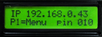
P3 button shows the IP address of Raspberry Pi and the status of the three additional input pins
-
P4 shows the CPU usage
-
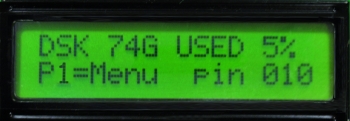
P5 shows the space on the SD Card or hard disk, both in GB and percentage
-
P6 shows the number of processes running





Pingback: Una placa de expansión con pantalla LCD para la Raspberry Pi - Raspberry Pi | Hardware